
6V Gel Cell Battery Charger

The battery charger schematic for a 6V Gel Cell battery type is designed to efficiently manage the charging process of rechargeable lithium batteries. The circuit utilizes a constant current approach, delivering 60 mA to AA cells until a voltage threshold of 2.4V per cell is reached. This method ensures that the batteries are charged safely and effectively, preventing overcharging, which could damage the cells. The inclusion of resistors such as R1 through R7 and capacitors C1 and C2 helps to stabilize the circuit and filter any noise, contributing to a smooth charging operation.
The Lead-Acid battery charger circuit complements the Gel Cell design by providing an initial charging voltage of 2.5V per cell at a temperature of 25°C. This initial voltage is crucial for quickly bringing the battery up to a functional charge level. As the battery charges, the circuit is designed to reduce the output voltage automatically when the charging current drops to 180 mA, further safeguarding the battery's health and extending its lifespan.
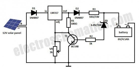
The solar-powered mobile phone battery charger is another innovative design that allows for charging from a lower voltage source, such as a solar panel. This circuit is particularly valuable in off-grid applications, where conventional power sources are unavailable. Care must be taken to ensure that the voltage produced by the solar panel exceeds that of the battery being charged, as attempting to charge with equal or lower voltage could lead to inefficiencies or damage.
The 12V NiCAD battery charger operates with a charging rate of 200 mA/hour, beginning at 75 mA until the battery reaches full charge. This gradual approach minimizes stress on the battery cells, allowing for a complete recharge within approximately four hours. The trickle charging phase ensures that the battery remains topped off without the risk of overcharging.
Lastly, the Ni-CAD Battery Charger circuit incorporates features for current and voltage limiting, which are essential for maintaining battery health over time. The visual indicators, such as lamp L1 and the LED, provide immediate feedback on the charging status, enhancing user interaction and safety. This comprehensive approach to battery management ensures optimal performance and longevity for various battery types.The following diagram is the battery charger schematic for 6V Gel Cell battery type. Component Parts List: R1 = 22 ohm, 1W R2 = 270 ohm R3 = 220 ohm *R4 = 715 ohm, 1% *R5 = 3. 57K, 1% *R6 = 1. 40K, 1% *R7 = 1. 47K, 1% C1 = 0. 1 F, ceramic C2 = 0. 1 F, ceramic. This battery charger circuit is used for rechargable lithium battery. Charging is accompli shed with a constant current of 60 mA for AA cells to a cutoff of 2. 4V per cell, at which point the charge must be terminated. The charging system shown is designed for multi-cell battery pack of 2 to 6 series connected cell. The following diagram is the circuit diagram of Lead-Acid battery charger. This circuit provides an initial voltage of 2. 5 V per cell at 25 ƒ to quickly charge the battery. The charging current decreases as the battery is charging, and when the current drops to 180 mA, the charging circuit reduces the output voltage of. This is the schematic diagram of solar powered mobile phone battery charger. The circuit is designed to charge the battery from a source with a lower voltage. Do not use it to charge the battery with the same or lower voltage than the voltage which is generated by the solar panel.
For proper operation of. The following diagram is the schematic diagram of 12V NiCAD battery charger with charging rate of 200mA/Hour. This NiCAD battery charger circuit charges the battery at 75 mA until the battery is charged, then it reduces the current to a trickle rate.
It will fully recharge a dead/unpowered battery in 4 hours and the battery. The following diagram is the schematic diagram of Ni-CAD Battery Charger circuit which featured with current and voltage limiting to keep the battery lifetime. The lamp L1 will be light brightly and the LED will be out when the battery is low and battery charging in progress, but the LED is very bright and the.
🔗 External reference
Related Circuits
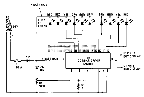
Most of the circuitry is contained in the LM3914 dot/bar-graph driver IC chip. In addition to the comparator circuitry within the package, it also contains a stable reference supply and the drivers for the LEDs. Resistor R2 acts as...
Nickel-Cadmium (NiCad) batteries serve as effective rechargeable power sources for portable devices. However, it is crucial to avoid damaging the batteries through overdischarge. Specifically, a NiCad battery should not be discharged to the extent that the cell polarity is...
This is a solar charger circuit designed to charge Lead Acid or Ni-Cd batteries using solar energy. The circuit captures solar energy to charge the batteries. The solar charger circuit typically consists of several key components, including a solar panel,...
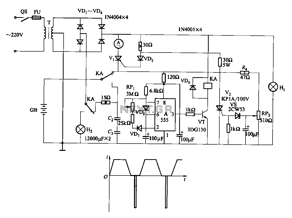
Fast and efficient charging is significantly higher than conventional charging, achieving a current charge that is ten to several times greater. When the battery voltage reaches a predetermined level (known as the polarization point), polarization within the cell becomes...
The charger is built around a LM317 adjustable regulator. The charge starts when a battery is connected between pins JP1-JP4 or JP2-JP4 or JP3-JP4. For example, if a battery is connected to JP1-JP4 pins then the current that flows...

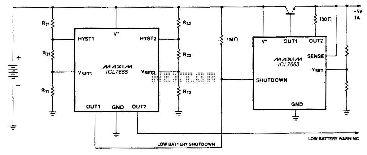
A common need in many systems is to obtain positive and negative supplies from a single battery. Where current requirements are small, the circuit shown is a simple solution. It provides symmetrical +&- output voltages, both equal to one...