
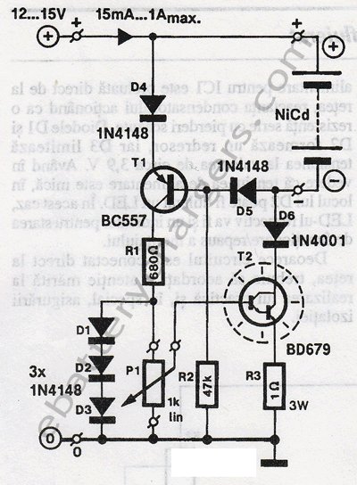
Quick NiCd - NiMH Charger

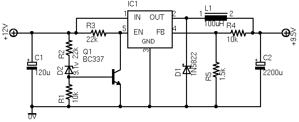
The input voltage must be at least 3 times the battery's voltage. For example, an input voltage of 25V can charge an 8.4V (9V) battery.
R3 is 1/2 Watt and R1 and R2 are 1/4 Watt.
The circuit utilizes the LM317 voltage regulator, which is a versatile component capable of providing a stable output voltage. The LM317 operates in the adjustable mode, allowing it to regulate the output voltage based on the resistors R1 and R2, which are configured in a voltage divider arrangement. The adjustment pin of the LM317 is crucial for setting the output voltage, which in turn determines the charging current supplied to the connected battery.
When a battery is connected to any of the designated pins (JP1-JP4, JP2-JP4, or JP3-JP4), the charging process initiates. The current flowing through R1 creates a voltage drop, which is essential for the operation of the subsequent components in the circuit. The diode D1, with a forward voltage drop of approximately 0.7 volts, allows current to pass while blocking reverse current flow, ensuring that the battery does not discharge back into the circuit. The transistor Q1 acts as a switch controlled by the output from the LM317, allowing current to flow to the battery when it is charging.
Resistors R1, R2, and R3 play a critical role in determining the charging current. The formula provided, Rx=(1.25 + 0.1) / I, highlights how the resistance values can be calculated based on the desired charging current, which is set to 1/10 of the battery's capacity. This method ensures that the charging current is appropriate for the battery being charged, preventing overcharging or damage.
The design specifies that the input voltage must be at least three times the voltage of the battery to ensure proper operation of the LM317. For instance, a battery with a nominal voltage of 8.4 volts would require a minimum input voltage of 25.2 volts for effective charging.
Power ratings for the resistors are also specified, with R3 rated at 1/2 Watt and R1 and R2 at 1/4 Watt, ensuring that they can handle the power dissipation without overheating during operation. This attention to component ratings is essential for the reliability and longevity of the charging circuit.The charger is build around a LM317 (click to download datasheet) adjustable regulator. The charge starts when a battery is connected between pins JP1-JP4 or JP2-JP4 or JP3-JP4. For example, if a battery is connected to JP1-JP4 pins then the current that flows cause a voltage drop to R1, then D1 causes a voltage drop of 0,7 volts and ?1 conducts. Then through transistor's emitter flows a current that comes from Adjustment pin of LM317. Diode D4 prevents current to flow from battery back to the charging circuit. Resistors R1,R2 and R3 adjusts the charging current and it's value is given from : Rx=(1,25 + 0,1) / I , where x = 1,2,3.
I is 1/10 of the battery's charging capacity. For example if battery has a rated capacity of 1700mA then ?=170. The input voltage must be at least 3 times the battery's voltage. For example an input voltage of 25V can charge a 8,4V (9V) battery. R3 is 1/2 Watt and R1 and R2 it's 1/4 Watt. 🔗 External reference
Related Circuits
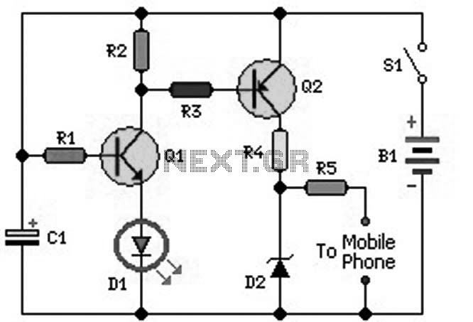
An ideal mobile charger utilizing 1.5-volt pen cells to charge mobile phones while traveling. This charger can replenish a cell phone battery three to four times in locations where AC power is unavailable. Most mobile phone batteries are rated...
This 24V to 36V linear battery charger is long overdue. While this is an old circuit technique, it is optimized for charging higher voltage lead-acid batteries. The 24V to 36V linear battery charger is designed to provide a stable charging...
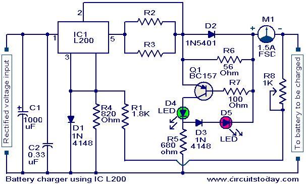
A simple battery charger circuit with reverse polarity indication is presented here. The circuit utilizes the L200 integrated circuit (IC), which is a five-pin variable voltage regulator. The charging circuit can be powered by DC voltage from either a...
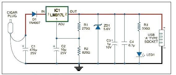
This USB car charger adapter project functions as a DC-DC power converter that effectively converts the 12V car battery voltage into a stable 5V output. It is designed to supply power from a car's cigar lighter socket to any...
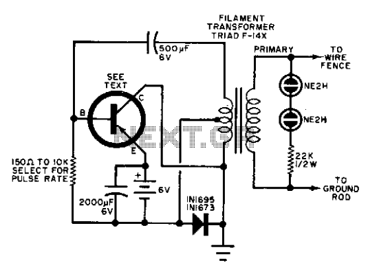
Any suitable power transistor can be utilized in this circuit. The base resistor must be calibrated to achieve a pulse rate of approximately 50 pulses per minute, with a possible range from 10 to 100 pulses per minute. The...
The ASUS Eee is an ultra-portable notebook that meets the essential needs of tech enthusiasts while maintaining excellent build quality and affordability. In New Zealand, it can be purchased exclusively from DSE, where it is competitively priced compared to...