
6v to 12v converter

When the output of IC1 is at zero, the C4 charges via the diode D1 up to the power supply level minus the voltage drop at D1. When the IC1 swings to the opposite direction, its output becomes positive. The output voltage from IC1 adds up to the voltage stored at C4 forcing the diode D1 to stop conducting. C5 then charges via the diode D2 to a voltage that is double the power supply level.
The theoretical output could reach triple the supply voltage. To guard against unnecessary voltage increases at low current consumptions, a limiter stage was added to the circuit composed of a 15-volt zener diode and a Darlington transistor T1/T2. This stage caps the output voltage to about 14.2 volts. To filter out ripple from the output, C8 was also added. This helps prevent the hum signal from being noticed on radio or audio devices.
In constructing the 6 to 12 volts converter, attach the ICs to a common heatsink close to the PCB. The transistor must be attached to a separate heatsink. To get a much higher current output from the converter, C4, C5, and C6 must be increased to 2200uF.
The 6V to 12V converter circuit utilizes a TDA2003 integrated circuit (IC), which is a power amplifier designed for automotive applications, but can also function as a multivibrator in this context. The circuit operates on the principle of pulse width modulation to generate a higher output voltage from a lower input voltage. The frequency of oscillation is critical for the performance of the converter; at no load, the circuit oscillates at approximately 4 kHz, which increases to around 7 kHz under load conditions. This frequency is determined by the capacitor C3, which influences the timing characteristics of the multivibrator.
The architecture includes two operational amplifiers, IC1 and IC2. IC1 serves as the primary oscillator, while IC2 generates an inverted output signal. The interaction between these two signals facilitates the charging and discharging of capacitors C4 and C5. The charging process occurs through diodes D1 and D2, which allow current to flow in one direction only, ensuring that the capacitors store energy effectively.
The output voltage regulation is managed by a combination of a zener diode and a Darlington pair transistor (T1/T2). This regulation prevents excessive voltage output, particularly under low-load conditions, thus enhancing the reliability and safety of the circuit. Capacitor C8 acts as a filter to smooth out any ripple in the output voltage, which is particularly important in audio applications to avoid hum and noise.
Thermal management is an important consideration in the design, necessitating the use of heatsinks for both the ICs and the Darlington transistor to dissipate heat generated during operation. For applications requiring higher current output, the values of capacitors C4, C5, and C6 should be increased to 2200 µF, which will enhance the energy storage capacity and improve the overall performance of the converter. This design approach provides a cost-effective solution for converting 6V to 12V without the complexity of transformers, making it suitable for various electronic applications.This 6V to 12V converter circuit is made with an IC from SGS with several additional components. The IC is a TDA2003 but it can be replaced with a TDA2002. The cost of building the 6volts to 12 volts converter should be low enough to justify constructing it instead of modifying the entire equipment setup to work directly with a 6 volts power supply. The two principles of simplicity and functions properly without the need of the transformer. The IC1 opam functions as a stable power multivibrator. Its oscillation frequency is determined by C3. Its oscillates at around 4kHz at standby and increases in a loaded condition up to around 7kHz. The output of the IC2 opamp is identical to the IC1 oscillator signal but in the opposite phase. When the output of IC1 is at zero, the C4 charges via the diode D1 up to the power supply level minus the voltage drop at D1. When the IC1 swings to the opposite direction, its output become positive. The output voltage from IC1 adds up to the voltage stored at C4 forcing the diode D1 to stop conducting.
C5 then charges via the diode D2 to a voltage that is double than the power supply level. The theoritical output could reach the triple of the supply voltage. TO guard against unnecessary voltage increases at low current consumptions, a limiter stage was added to the circuit composed of a 15 volt zener diode and a darlington transistor T1/T2. This stage caps the output voltage to about 14.2 volts. To fiter out ripple from the output, C8 was also added. This helps prevent the hum signal from being noticed on radio or audio devices. In constructing the 6 to 12 volts converter, attach the ICs to a common heatsink close to the pcb. THe transistor must be attached to a separate heatsink. To get a much higher current output from the converter, C4, C5 and C6 must be increased to 2200uF. 🔗 External reference
Related Circuits
This is a circuit for a Voltage-to-Pulse Duration Converter. The circuit is designed to convert voltage into pulse duration by integrating a timer IC and an operational amplifier (OP Amp). The Voltage-to-Pulse Duration Converter circuit utilizes a timer IC, typically...
A 40-watt fluorescent tube lamp or two 20-watt tubes in series will be driven by this circuit. The transformer is wound on a ferrite rod with a diameter of 10 mm and a length of 8 cm. The circuit described...
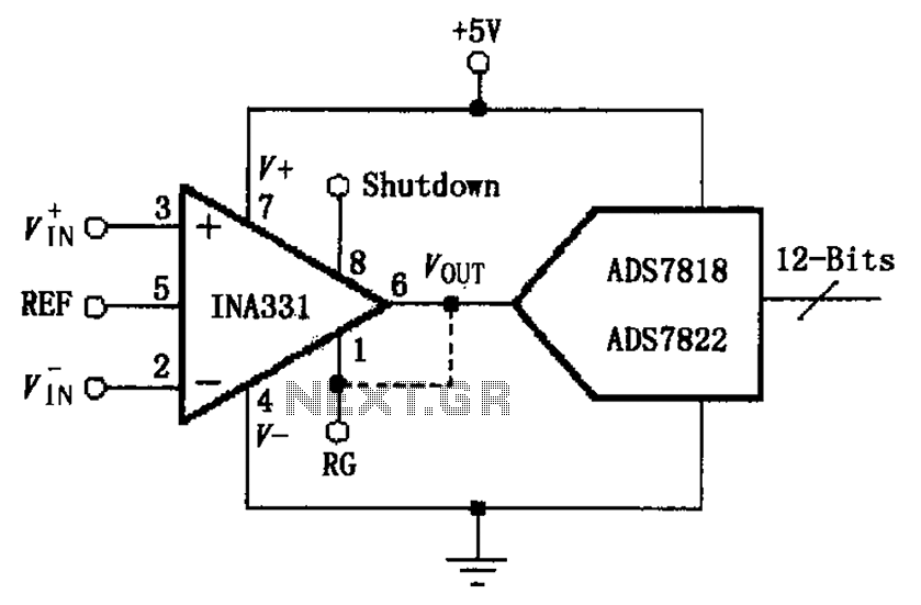
The INA331/332 is configured to directly drive a capacitive input A/D converter. Due to the low output resistance of the INA331/332, it is capable of operating at high frequencies and can directly handle capacitive loads. The output voltage from...
This is a simple 12 volts DC to AC inverter circuit. The 120V AC power source is constructed using a basic 120V:24V or 110V:24V center-tapped control transformer. The described inverter circuit converts a 12V DC input into a 120V AC...
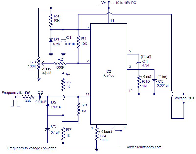
A simple and low-cost frequency-to-voltage converter based on the TC9400 IC from Microchip is presented. The TC9400 can be configured as either a voltage-to-frequency converter or a frequency-to-voltage converter, requiring minimal external components. The internal functional blocks of the...
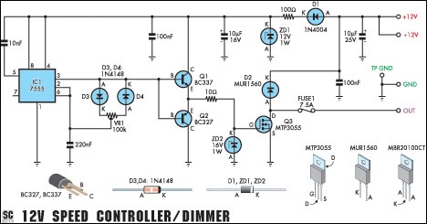
This circuit serves as a speed controller for a 12V motor with a continuous rating of up to 5A or as a dimmer for a 12V halogen or standard incandescent lamp rated up to 50W. It regulates power to...