
DC to AC Inverter - 12V to 110V/120V Inverter

The described inverter circuit converts a 12V DC input into a 120V AC output, which is suitable for powering standard household appliances. The core component of this inverter is a center-tapped transformer, which plays a crucial role in stepping up the voltage from 24V (or 12V from each side of the center tap) to the desired 120V AC.
The circuit typically includes a switching mechanism, which can be implemented using transistors, MOSFETs, or a combination of both, to alternate the current direction through the primary winding of the transformer. This switching action creates an alternating magnetic field, inducing an alternating voltage in the secondary winding of the transformer.
To ensure the inverter operates efficiently, the switching frequency should be optimized, typically in the range of several kilohertz. This frequency is critical as it affects the transformer size and efficiency. Additionally, feedback mechanisms may be incorporated to regulate the output voltage and maintain stability under varying load conditions.
Protection features such as fuses and thermal cutoffs should be included to safeguard against overcurrent and overheating, which could damage the components or lead to circuit failure. The circuit may also include filtering capacitors at the output to smooth the AC waveform, reducing harmonic distortion and providing cleaner power to connected devices.
Overall, this inverter design is a practical solution for applications requiring a compact and efficient method to convert low-voltage DC power into usable AC power for various electronic devices.Here is a simple 12 volts DC to AC inverter circuit. This 120V AC power source is built with a simple 120V:24V or 110V:24V center-tapped control transforme.. 🔗 External reference
Related Circuits

This inverter circuit is designed to power electric razors, stroboscopes, flash tubes, and small fluorescent lamps using a 12-volt car battery. Unlike typical feedback oscillator inverters, this design features a separate oscillator from the output stage, allowing for easy...
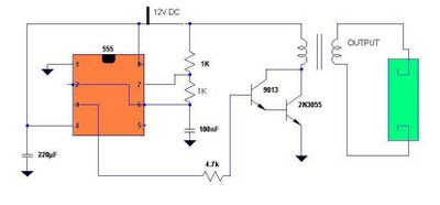
Fluorescent tubes contain mercury, which poses health risks. Improper disposal of these tubes is harmful to both the environment and health; therefore, recycling is a beneficial option. The 555 timer IC is utilized to generate a square wave voltage...
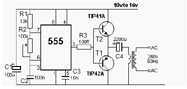
This 12V power inverter circuit can be utilized to supply power to small devices that require 240 volts. It is particularly beneficial when there is a need to operate equipment designed for 240 volts. The 12V power inverter circuit is...
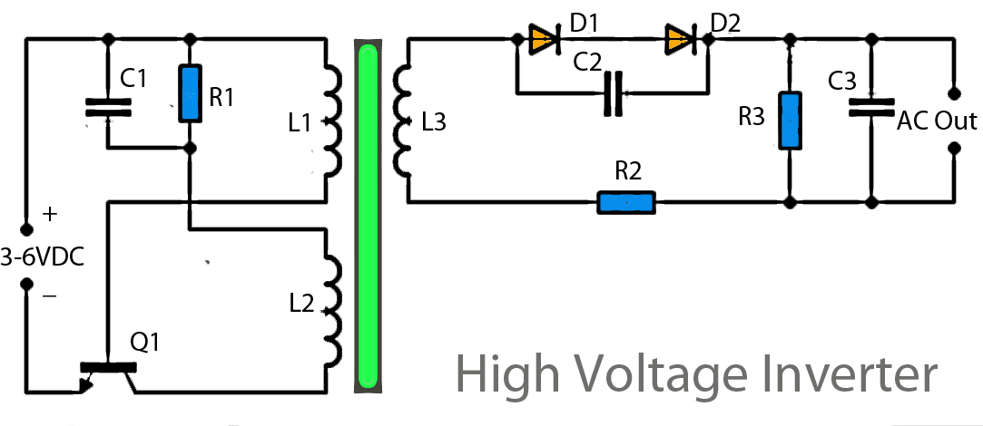
This inverter circuit operates using a transistor and transformer, along with other components, to elevate the voltage. The input supply voltage ranges from 3V to 6V DC, which is then converted to a high voltage AC output. However, the...
This document presents a straightforward and practical schematic for a 12V to 3V converter circuit. The output current of the circuit is approximately 1A. The 12V to 3V converter circuit is typically designed using a linear voltage regulator or a...
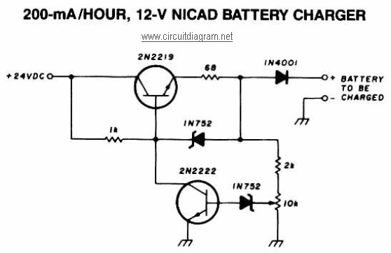
A 12V NiCAD battery charger circuit with a charging rate of 200mA per hour. This circuit initially charges the battery at 75mA until it reaches a full charge, after which the current is reduced to a trickle rate. The...