
quick counter for young

The circuit utilizes a combination of digital logic components and timing circuits to create an interactive counting experience for children. The 4049 hex inverter serves as the core oscillator, generating clock pulses that synchronize the operation of the shift registers. The 4015 shift registers are crucial for controlling the sequential illumination of the LEDs, allowing for a random selection of lit outputs that can be visually counted by children.
The integration of the 7555 timer in monostable mode enhances the user experience by providing a controlled viewing period for the counted LEDs. The adjustable viewing time, facilitated by VR1, allows for tailored interaction based on the child's counting ability. The use of push buttons PB1 and PB2 provides a simple and intuitive interface for children to engage with the toy, reinforcing their counting skills through interactive play.
The design also emphasizes variability and unpredictability in the counting process, as the arrangement of the LEDs and the random selection mechanism ensure that each counting session is unique. This unpredictability, coupled with the non-linear arrangement of the LEDs, encourages children to focus on counting rather than relying on visual patterns, thus enhancing their cognitive skills in a playful manner.
Overall, this circuit presents a creative and educational tool that combines electronics with early childhood learning, making it an effective aid for teaching counting in an engaging way.This circuit is a toy to encourage young children to count. Power is turned on by switch S1, then S2 is closed. This makes nine LEDs flash slowly. S2 is then opened and the LEDs go out. Pressing push-button PB1 turns on a random number of LEDs - briefly - during which time they are to be counted. The number counted can be checked by pressing PB2 w hich turns the same LEDs on for as long as needed. Then repeat. The circuit works as follows: IC3 is a 4049 hex inverter connected as three oscillators running at different rates. It is turned on by closing switch S2a. The clock pulses from IC3 drive both halves of IC1 and one half of IC2, both being 4015 dual 4-stage shift registers.
Each shift register has four outputs which go high in order: 1, 1 and 2; 1 and 2 and 3; 1 and 2 and 3 and 4. However as output 4 is connected to the reset line of its own half - the shift register resets to zero.
Outputs 1, 2 & 3 of all three shift registers are connected to nine LEDs, the cathodes of which go to a common rail. This rail is connected to ground via S2b when switch S2 is closed. When S2 is opened the three oscillators stop but a random number of LEDs is still connected to the high outputs of the 4015s.
That number can be viewed briefly by pressing PB1 which pulses the 7555 timer in monostable mode, to give a short duration output which drives Q1 and connects the LED cathodes to 0V. The viewing time is adjustable by VR1. Checking a count is done by pressing PB2 which holds the same LEDs on as long as desired. The LEDs are set in a 3 x 3 grid with the connection scattered, ie, the first row is not the three LEDs from the first half of IC1.
Note that, unlike the usual dice, a number such as 5 can appear in many formats, so pattern recognition is no help. Also note that this is not a nine output true dice - because the numbers do not come up with equal frequency.
🔗 External reference
Related Circuits
The object of Quick Draw is to test your reaction time against your opponent's. A third person acts as a referee and begins the duel by pressing S1, which lights LED1. Upon seeing LED1 go on, you try to...

The schematic for this project is visually acceptable, although it is not the most refined layout for a schematic. The basic flow progresses from left to right, starting with the state machine, followed by the 555 timers, then the...
This is a schematic and block diagram of a 2-MHz frequency counter. It employs an LSI counter/display driver, an LCD readout, and several logic chips for timebase and timing pulse circuitry. Transistors Q2 and Q3 form a signal input...
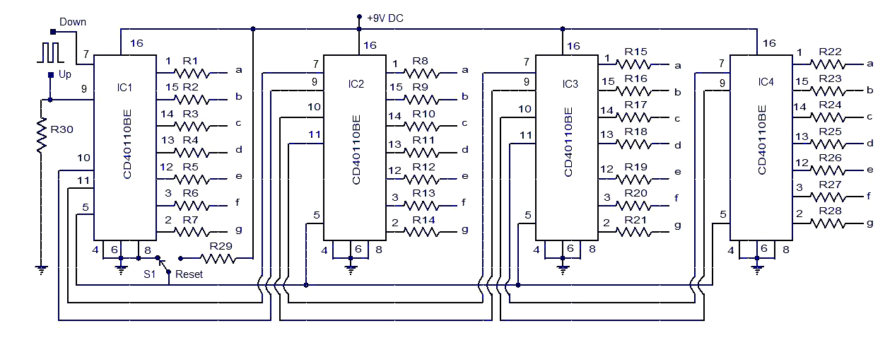
This circuit diagram illustrates a simple up/down counter suitable for various applications. It utilizes the CD40110BE IC, a CMOS decade up/down counter. Common cathode seven-segment displays are connected to the outputs of each IC. The display connected to IC1...

This is an adaptation of the previously posted bicycle anti-theft alarm. A commenter expressed interest in modifying it for use with a threshold step plate vibration detector. The adaptation of a bicycle anti-theft alarm into a threshold step plate vibration...
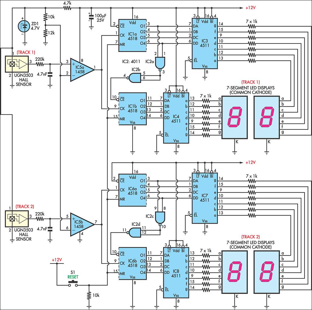
AFX slot car sets are enjoyable, and the experience can be enhanced with a lap counter. This circuit counts from 00 to 99, featuring independent counters for each track. The sensing device utilized is a Hall effect sensor (UGN3503),...