
555 square wave generator

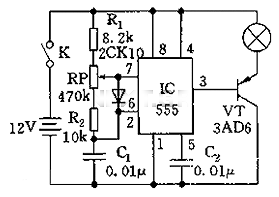
The square wave generator circuit typically consists of a few key components: a timer IC, such as the 555 timer, resistors, capacitors, and possibly a diode for protection. The 555 timer can be configured in astable mode to produce a continuous square wave output. This output is characterized by its alternating high and low voltage levels, which can be adjusted by changing the values of the resistors and capacitors in the circuit.
In an astable configuration, the 555 timer oscillates between its high and low states, generating a square wave signal. The frequency of the output waveform is determined by the formula:
\[ f = \frac{1.44}{(R1 + 2R2)C} \]
where \( R1 \) and \( R2 \) are the resistances connected to the timer, and \( C \) is the capacitance of the timing capacitor. By selecting appropriate values for \( R1 \), \( R2 \), and \( C \), the desired frequency for the speedometer can be achieved.
The output from the 555 timer can then be connected to the speedometer circuit board. This output may require buffering if the load is significant or if the input of the speedometer circuit cannot handle the output directly. A transistor can be used to amplify the signal if necessary.
Additionally, it is important to ensure that the power supply voltage levels are compatible with both the 555 timer and the speedometer circuit to prevent damage. Proper decoupling capacitors should also be included near the power pins of the 555 timer to ensure stable operation.
In summary, the square wave generator serves as a fundamental building block for driving the speedometer circuit, providing a reliable and adjustable frequency output necessary for accurate speed measurement.Hello, Please help me, I have designed a very basic square wave generator to run a speedometer circuit board which is providing output to control a.. 🔗 External reference
Related Circuits
Adding this combination audio circuit, as illustrated in figure 14-38, to the automatic rhythm generator of electronic musical instruments fulfills the players' demand for incorporating drum and cymbal audio, enhancing the overall performance effect. The diagram indicates that the...
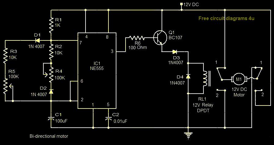
This circuit illustrates a bi-directional motor control circuit utilizing the NE555 integrated circuit (IC). Features include a 12V DC power supply, with the IC employed to control relay RL1. The bi-directional motor control circuit designed with the NE555 IC allows...

A project is underway that necessitates the conversion of a 0-10V DC supply into a linear frequency range in the form of a square wave. The project involves designing a circuit that takes a direct current (DC) voltage input ranging...
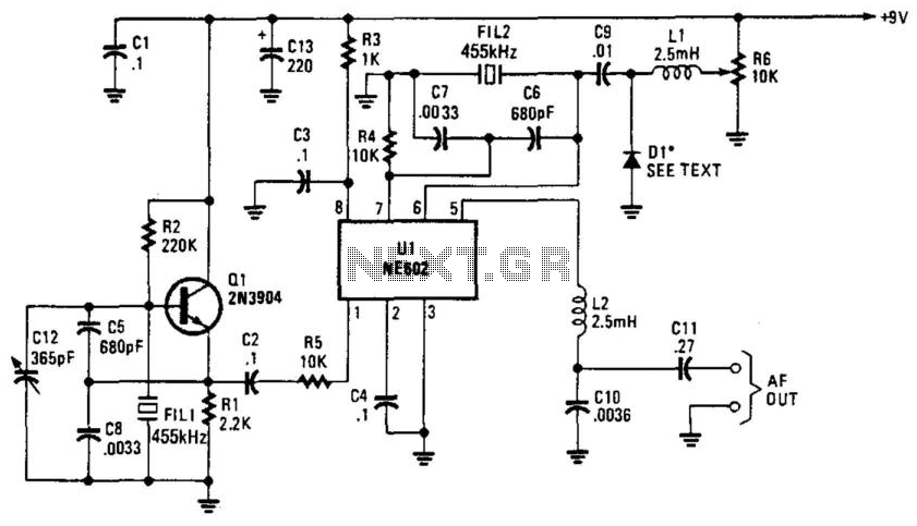
Q1 is a fixed oscillator operating at 455 kHz. U1 is a mixer with its own internal oscillator running at 45.5 kHz. FIL1 and FIL2 are Murata CSB455E filters or equivalent. D1 is a varactor diode (an IN4002 used...
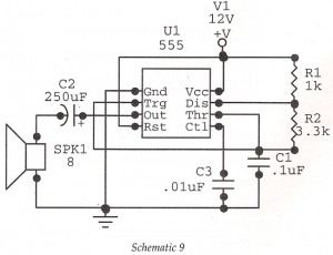
This circuit features an astable oscillator constructed around a 555 timer, generating an alarm tone of 1.8 kHz, which directly drives a speaker. It serves as a fundamental alarm circuit that can be utilized in various projects. Although the...
The circuit illustrated in the figure is a dimmer using the 555 timer as the core component. The 555 timer, along with resistors R1, RP, R2, and capacitor C1, forms an astable multivibrator. The oscillation frequency, f, is calculated...