
voltage to frequency converter icl8038

The circuit utilizes the ICL8038 waveform generator, known for its precision in generating sine, square, triangular, and pulse waveforms. In this application, it produces square wave pulses that serve as timing signals for the CD4040 binary counter. The CD4040 is a 12-stage binary ripple counter that can count pulses and is capable of operating from a dual power supply, making it suitable for this configuration.
The tachogenerator provides feedback by generating a voltage proportional to the speed of the motor driving the conveyor. This feedback voltage is essential for monitoring the operational speed and ensuring accurate counting of impacts. The voltage is conditioned through attenuation and filtering to prevent noise from affecting the measurement and to ensure compatibility with the input requirements of the ICL8038.
Resistors R10 through R15 are part of a voltage divider network that ensures the correct voltage levels are maintained for the logic circuitry. The inclusion of transistor Q1 serves to buffer the output, allowing the circuit to drive loads effectively while maintaining the integrity of the pulse signals. The virtual ground concept allows the circuit to operate efficiently in a bipolar supply configuration, ensuring that the logic levels are appropriately referenced.
Overall, this circuit exemplifies a well-integrated design that combines waveform generation, feedback control, and counting mechanisms, making it a robust solution for impact counting applications in industrial settings.This was a small circuit made for driving an Impact counter. The heart being ICL8038. It must have been a Motor driving a Conveyor, the motor has a feedback attachment called Tachogenerator. Only part of the circuit is shown here. See the image of product here Tacho Counter. The configuration is derived from the Application Notes of Intersil. T he Voltage from Tachogenerator is Measured on a DPM-DVM and also fed to this circuit after attenuation and filtering. The square pulses of 8038 is used to derive a Logic pulse train for a CD4040. The CD4040 works of 0 and 12V. The above circuit is on +12 and -12. That is the reason R10-R15-Q1 are used. The pulses are 0-12V pulses. The Zero is Virtual like the Virtual Ground in low current power supplies. 🔗 External reference
Related Circuits
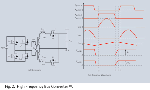
Distributed power systems are commonly used in telecommunications, networking, and high-end server applications, utilizing a 48 V bus voltage derived from the telecom industry. This 48 V bus supplies several isolated point-of-load (POL) converters that power the end loads,...
The circuit is a direct-reading frequency meter that utilizes an amplifier and a one-shot trigger circuit, along with table-top components. It is capable of directly detecting a 1mA signal at the read head, with a maximum signal frequency of...
A low-frequency oscillator (Q1) modulates a high-frequency oscillator (Q2) along with its associated timing capacitor. The output frequency varies continuously. The circuit comprises two primary components: the low-frequency oscillator (Q1) and the high-frequency oscillator (Q2). The low-frequency oscillator is responsible...

The two circuits illustrate the generation of low-frequency sine waves by shifting the phase of the signal through an RC network, enabling oscillation when the total phase shift reaches 360 degrees. The transistor circuit on the right produces a...
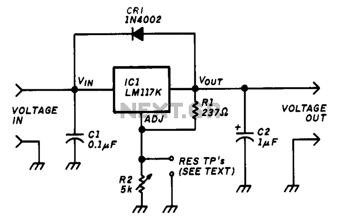
The variable voltage regulator allows for the adjustment of the output voltage of a fixed DC power supply between 1.2V and 37V DC, with the capability to supply output currents exceeding 1.5A. The circuit utilizes an LM117K three-terminal adjustable...
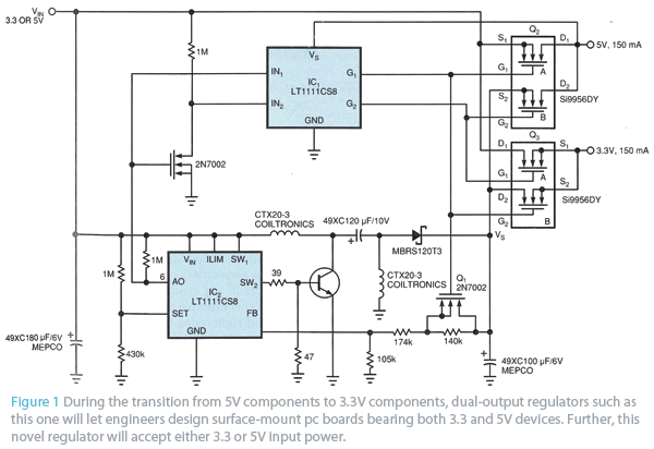
The circuit in Fig 1 provides both 3.3V and 5V power to transitional circuits that utilize both newer 3.3V devices and older 5V devices. Additionally, due to the regulator... The circuit illustrated in Fig 1 is designed to accommodate the...