
741 Astable Timer

The astable multivibrator configuration using an op-amp, such as the 741, creates a square wave output without requiring any external triggering. The circuit's operation is based on the charging and discharging cycles of the capacitor C1 through the resistor U2. As the capacitor charges through the resistor, the voltage across it rises until it reaches a threshold determined by the op-amp's internal reference levels. At this point, the op-amp switches its output state, causing the capacitor to discharge through the resistor, resulting in a square wave output.
In this case, the variable resistor allows for fine-tuning of the frequency of oscillation. By adjusting the resistance value, the time constants for charging and discharging the capacitor change, directly affecting the frequency of the output waveform. The output frequency can be calculated using the formula:
\[ f = \frac{1}{T} = \frac{1}{(R \cdot C \cdot \ln(2))} \]
Where \( R \) is the resistance in ohms, \( C \) is the capacitance in farads, and \( T \) is the period of the waveform. The non-symmetrical nature of the output waveform indicates that the time spent in the high state differs from the time spent in the low state, which can be beneficial for certain applications that require specific duty cycles.
The op-amp's high gain ensures that the output transitions are rapid, contributing to the low rise and fall times observed in the output waveform. This characteristic is particularly advantageous in applications where fast switching is essential, such as in pulse-width modulation (PWM) or timing applications.
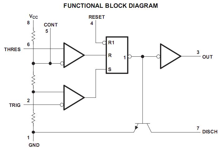
It is important to ensure that the op-amp is powered correctly, and the input pins are connected appropriately to avoid damage. The output can be interfaced with other components in a circuit, such as LEDs, transistors, or microcontrollers, for various applications, including signal generation, clock pulses, and timing applications.In this circuit a standard op-amp is wired as an astable multivibrator. The output is non-symmetrical but has the advantage that the timing is controlled by only 1 resistor and capacitor, in this case, the 100k variable resistor, U2 and 100u capacitor C1. Because of the high loop gain the output rise and fall times are very low, slope times better than 30uS can be acheived even with a 5V supply. Waveforms are shown below: The green trace is the output voltage at Pin 6 of the op-amp, the blue trace is the voltage at Pin C and also the charge and discharge of C1, and the voltage at the op-amps pin 3 is shown in red. The pinout for the 741 is shown below: Please note that the the inverting input is pin 2 and non-inverting input is pin 3 on the in the schematic.
The timing is shown below. The "on" time is for a positive half cycle, "off" time is the negative cycle, although being run from a single supply, the off voltage is slightly higher than 1 Volt. The frequency is the reciprocal of one half postive and one half negative cycle. 🔗 External reference
Related Circuits
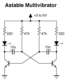
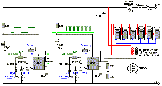
Two 47k ohm resistors, with alternative values ranging from 22k to 100k ohm, can be used. The value of these resistors affects the timing of the blinking; larger values result in slower blinking. In a typical electronic circuit designed for...
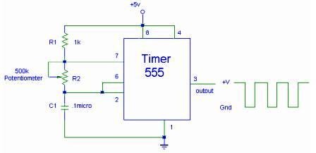
The setup for the Square Wave Generator can be initiated using a 555 timer IC as illustrated in the accompanying circuit diagram. It is essential to reference the pinout configuration of the 555 timer IC. An oscilloscope should be...
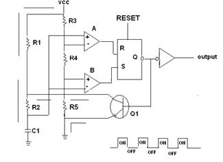
A 555 timer IC is utilized as an astable multivibrator, as illustrated in the accompanying figure (A). The threshold input is connected to the trigger input (Pin 2). The resistor R1, resistor R2, and capacitor C1 form the timing...
Considering the rapid advancements in the electronics industry, the 555 timer could be regarded as a constant in an ever-evolving landscape. What exactly is the 555 timer? How does it function? In what ways can it be utilized? And...
How to create a hydrogen generator using a 555 timer circuit with Pulse Width Modulation (PWM). This PWM circuit can generate hydrogen on demand. The hydrogen generator circuit utilizing a 555 timer operates by controlling the duty cycle of the...
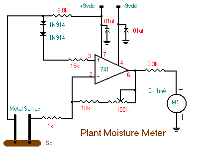
The following circuit illustrates a Plant Moisture Meter Circuit Diagram. This circuit is based on the LM741 integrated circuit (IC). Features include a meter that indicates moisture levels. The Plant Moisture Meter Circuit utilizes the LM741 operational amplifier to measure...