
7555 IC For 5 To 30 Minute Timer
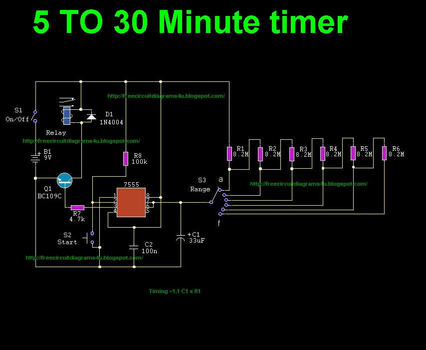
The 7555 timer IC is a versatile component that can be configured in various modes, including monostable and astable configurations. In the context of a timer circuit, it is typically used in a monostable mode where it generates a single output pulse of a specified duration in response to a triggering input.
To construct a 5 to 30-minute timer using the 7555 IC, the circuit will typically include the following components: the 7555 timer IC, resistors, capacitors, and a power supply. The timing duration is primarily determined by the resistor-capacitor (RC) network connected to the timing pins of the IC.
In this configuration, the timing capacitor (C) is charged through a resistor (R), and the time period (T) can be calculated using the formula T = 1.1 * R * C. By selecting appropriate values for R and C, the desired timing range can be achieved. For example, to achieve a 30-minute timer, a larger capacitor value or a higher resistance value may be necessary.
The output of the 7555 can be connected to various loads, such as LEDs, relays, or other devices that require timed activation. Additionally, the circuit may incorporate a manual reset switch to allow the user to reset the timer before the timing period elapses.
Overall, the 7555 timer circuit is a practical solution for applications requiring delayed activation, making it suitable for various electronic projects and automation tasks.Description:This circuit shows about 7555 IC For 5 To 30 Minute Timer Circuit Diagram. Features: useful circuit because by using this circuit you can operate .. 🔗 External reference
Related Circuits

This is a simple 555 timer circuit suitable for oscillating applications. To slow down the strobe effect, replace the 220 µF capacitors with 1000 µF capacitors. For a faster strobe effect, use a 150 µF capacitor. Additionally, R1 can...
This project is a basic code practice oscillator designed for beginners to learn Continuous Wave Morse Code. It utilizes a 555 timer to produce a "dit" or "dah" sound when the key is pressed. The circuit employs a 555 timer...
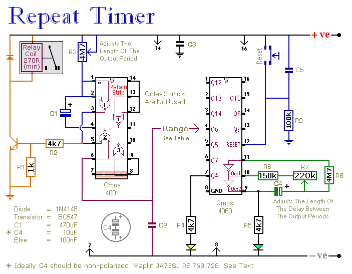
This circuit features an adjustable output timer capable of re-triggering at regular intervals. The output duration can range from a fraction of a second to over half an hour, and it can be configured to recur at regular intervals...

This coil gun design utilizes arbitrary on/off times that are calculated based on the basic equations of motion, rather than chosen randomly. The coils do not activate at uniform intervals; the first coil remains energized for the longest duration...
The question sometimes comes up of how to cascade 4017 decade counters for more than 10 sequential stages. The LED sequencer below shows a possible solution using a few extra parts. When power is applied, the 15K resistor and...
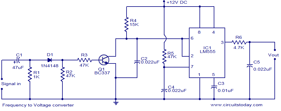
A simple frequency to voltage (F to V) converter circuit utilizing the LM555 Timer IC. This circuit has numerous applications in digital frequency meters, tachometers, and other related devices. The frequency to voltage (F to V) converter is a crucial...
Warning: include(partials/cookie-banner.php): Failed to open stream: Permission denied in /var/www/html/nextgr/view-circuit.php on line 713
Warning: include(): Failed opening 'partials/cookie-banner.php' for inclusion (include_path='.:/usr/share/php') in /var/www/html/nextgr/view-circuit.php on line 713