
7806IC For Automatic Battery Charger Circuit DIagram

The automatic battery charger circuit utilizing the 7806 integrated circuit (IC) is designed to provide a stable output voltage suitable for charging a 12V lead-acid battery commonly found in automobiles. The 7806 IC is a voltage regulator that outputs a fixed 6V, which can be advantageous for charging applications when configured appropriately.
In this circuit, the 7806 is connected to an AC to DC power supply, which converts the mains voltage to a lower DC voltage. This DC voltage is fed into the input pin of the 7806. The output pin of the IC is then connected to the battery, enabling it to charge effectively. To ensure proper operation, it is important to include filtering capacitors at the input and output of the 7806 to stabilize the voltage and minimize ripple.
Additionally, a diode is typically placed in parallel with the battery to prevent reverse current flow when the charger is not in operation. A current-limiting resistor may also be included to protect the circuit from excessive current draw, especially during the initial charging phase when the battery voltage is significantly lower than the output voltage of the charger.
Thermal considerations are crucial in this design, as the 7806 can dissipate heat during operation. A heat sink may be necessary to prevent the IC from overheating, especially when charging a battery that is deeply discharged.
Overall, this circuit design effectively utilizes the 7806 IC to create a reliable automatic battery charger suitable for car batteries, ensuring safe and efficient charging under various conditions.This circuit shows about 7806IC For Automatic Battery Charger Circuit DIagram . Features: designed for a car battery (about 40 Ah rating), used .. 🔗 External reference
Related Circuits

This is a UHF band TV antenna preamplifier circuit with a gain of 15 dB, built using a BF180 UHF transistor. The circuit is straightforward in design. The operational principle consists of two stages. The first stage features a...
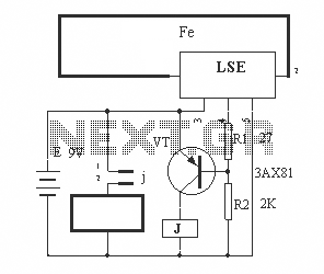
The circuit operation principle of the device illustrated in the figure is as follows: When the barbed wire is intact, the output pin of the LSE is high due to the absence of contact. Consequently, the transistor VT is...
The standard Class AB audio power amplifier allows for direct coupling of the amplifier's output to speakers. This is beneficial as it eliminates capacitors or transformers that could compromise sound quality. The speakers are connected directly to the amplifying...
The circuit below illustrates the use of the LM741 integrated circuit (IC) in a light and dark sensor configuration. This circuit offers several features, including a 1 Watt LED spotlight, making it suitable for a wide range of renewable...
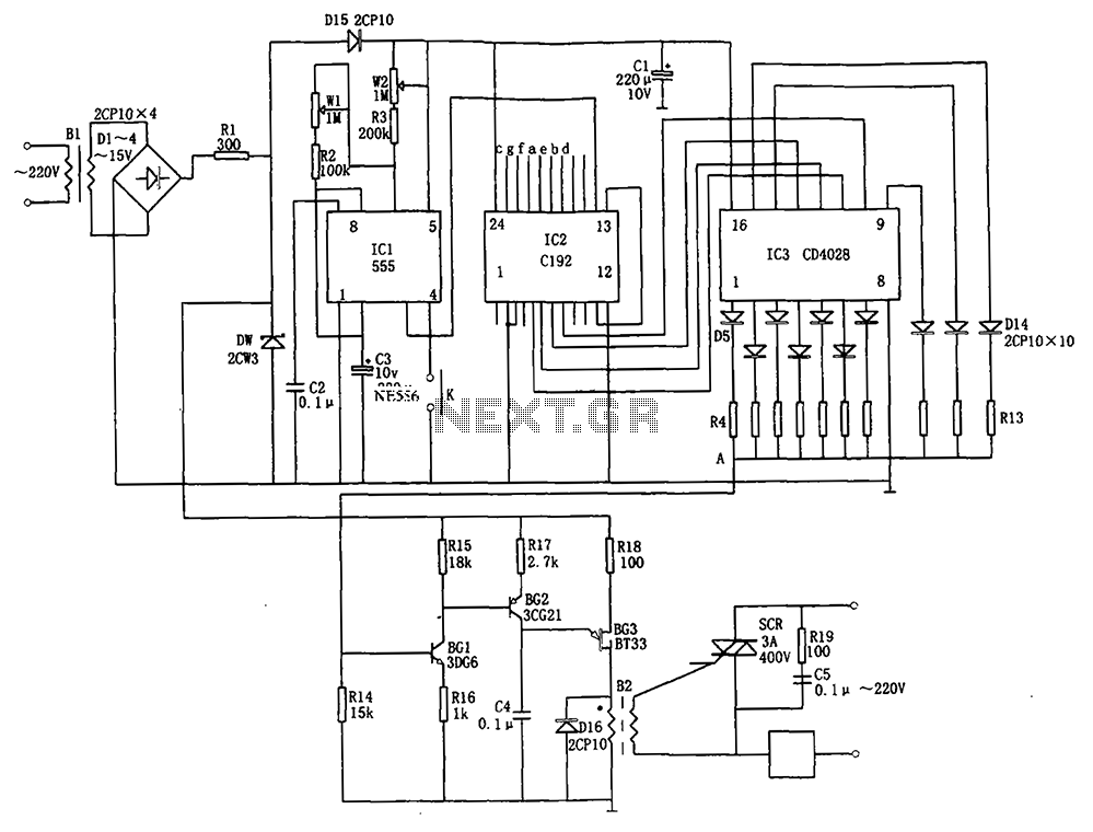
The automatic conversion circuit for wind speed control is depicted in Figure 10. This circuit consists of a clock signal generator (IC1), a counter (IC2), a decoder (IC3), a synchronous phase shifting circuit (BG1, BG2, BG3), a thyristor control...
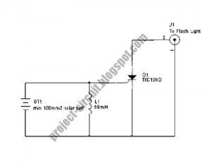
The following circuit illustrates a Slave Flash Light Control Circuit Diagram. Features include a 68mH inductor that provides an automatic trigger for the secondary flash light. The Slave Flash Light Control Circuit is designed to manage the operation of a...