
1Hz Oscillator circuit

The circuit begins with a quartz crystal oscillator, which is a crucial element in generating precise frequency signals. The crystal oscillator operates at 32,768 Hz, a frequency commonly used in timekeeping applications due to its binary nature (2^15). This output is fed into a 14-stage ripple counter, specifically the 4020 IC, which effectively divides the input frequency by 16, resulting in a 2 Hz output.
To further refine the frequency, the 2 Hz signal is processed by a JK flip-flop, such as the 4027, which is configured in toggle mode. This configuration allows the flip-flop to divide the frequency by 2 again, yielding a stable 1 Hz output. The dual output capabilities of 1 Hz and 2 Hz provide flexibility for various applications, including digital clocks and timing circuits, where the 2 Hz signal can be utilized for visual indicators or other timing needs.
The physical layout of the circuit is designed for a stripboard with dimensions of 12x23 holes, which facilitates compact assembly and easy integration into various projects. The inclusion of an LED at the 1 Hz output serves as a user-friendly feature, providing a visual cue of the circuit's operation. The current-limiting resistor (R2) is essential to prevent excessive current from damaging the LED, and its placement may require careful consideration due to spatial constraints near the diode (D1).
For optimal performance, the circuit is designed to operate with a 9V power supply. If alternative voltage levels are employed, it is advisable to reassess the specifications of the current-limiting resistor and potentially recalibrate the oscillator to ensure consistent functionality. This circuit exemplifies a straightforward yet effective design for generating accurate timing signals suitable for a variety of electronic applications.This plugin uses a quartz oscillator which uses a crystal (X1), amongst other components to give a 32, 768Hz (32, 768=215) output. This is input to a 4020 14-Stage Ripple Counter, which divides this signal down by 214 to a 2Hz signal.
This 2Hz signal is then halved in frequency using a JK flip-flop ( 4027 ) configured as a toggle flip-flop. The outp ut from this is used as the 1Hz signal. Both the 1Hz and 2Hz signals are taken as outputs, as the faster 2Hz signal is sometimes useful for clocking circuits at a visible speed, without going too slowly. Below is the stripboard layout for the plugin. The dimensions of the stripboard are 12x23 holes. An LED and current-limiting resistor have been added to the 1Hz output to provide a visual indicator.
This can be omitted without affecting the performance of the the circuit. R2 may need to be mounted around D1, as there is very little space for it. The parts lift below assumes a power supply of 9V. If a different voltage is used, it is possible that the LED current-limiting resistor (R2) must be changed and the oscillator may need adjustment as well. 🔗 External reference
Related Circuits

This circuit represents an FM transmitter, also referred to as an FM Bug, which consists of 18 essential components for optimal functionality. The circuit begins with an electret microphone on the far left side, and the signal flows electrically...
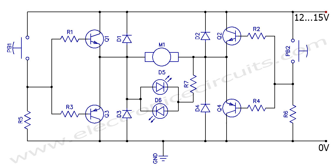
This circuit can control the direction of a DC motor, allowing it to operate in both clockwise and counterclockwise directions (forward and backward). The described circuit employs an H-bridge configuration, which is essential for reversing the polarity of the voltage...
This compact video transmitter is highly effective for short-distance video surveillance, operating efficiently up to 100 meters. It can be paired with either a black-and-white or infrared camera module, providing excellent image quality on standard color or black-and-white televisions....
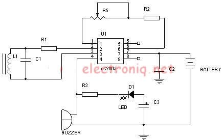
A simple metal detector electronic project circuit can be designed using the CS209A integrated circuit manufactured by Cherry Semiconductor. The CS209A integrated circuit is a bipolar monolithic integrated circuit intended for metal detection and proximity sensing applications. It incorporates...
This is the complete circuit of the modern homodyne receiver. This receiver can receive AM, CW, and SSB transmissions. The modern homodyne receiver is a sophisticated device designed to process various types of radio frequency signals, specifically Amplitude Modulated (AM),...

Collecting and storing experimental data presents a common challenge for hobbyists. A widely used method involves utilizing a device that converts analog data into digital format and stores the information on a computer. These devices are known as A/D...