
RF Probe and Watt Meter

The RF probe also facilitates measuring RF voltage, current, and power. While digital and analog multimeters can measure AC voltages, they are limited to a specific frequency range for accurate readings. For instance, a Maplin meter accurately measures frequencies up to 400Hz with 1% accuracy and up to 20KHz with 4% accuracy, provided the waveform is a sine wave. Beyond 20KHz, accuracy diminishes. A simple diode detector circuit suffices for measuring radio frequencies. The probe utilizes an OA91 germanium diode, which is preferred over silicon diodes due to its lower forward voltage drop of approximately 0.2V, compared to silicon's 0.6-0.7V. The diode rectifies the RF signal into a DC voltage that can be accurately read by a multimeter. A 1nF capacitor smooths the rectified DC signal presented to the meter.
When measuring AC or RF signals, the currents and voltages are in phase only with a purely resistive load. Transmitters are typically tested with a resistive dummy load, simplifying calculations. For example, a 1-watt transmitter delivers an average power of 1 watt into a 50-ohm resistive dummy load. The power (P) is measured in RMS or root-mean-square terms, with the relationship given by P = V²/R. Rearranging this equation provides V(rms) = sqrt(P x R). Power can also be expressed as P = I²R, leading to I(rms) = (P/R). Peak values are approximately 1.414 times the RMS values. Switch S1 allows for the selection of either a 50 or 75 ohm resistive load, enabling the probe to measure both loaded and no-load voltages. Given the fixed resistance of the load, the power delivered to it can be calculated.
The RF probe is capable of measuring output impedance of a transmitter by taking two readings: one unloaded and one under load at either 50 or 75 ohms. The output power measured by the probe may differ from the actual radiated power by the antenna due to losses in the antenna system and the Standing Wave Ratio (SWR). When the antenna and feedline impedances do not match, some electrical energy is lost in the system.
The RF probe provides four primary functions. In all cases, it should be connected between the circuit under test and the meter, which may include a transmitter, RF oscillator, or other signal source. Since the OA91 diode and the 10n capacitor form a half-wave rectifier, the RF value measured will reflect a peak value. To measure a transmitter voltage under load, S1 should be positioned to either the 50 or 75 ohm setting, with 50 ohm being the standard, while the 75 ohm setting is recommended for Band II (87.5MHz - 108MHz). For determining the output impedance of an unknown circuit or transmitter, both unloaded and loaded readings must be taken. The output impedance can then be calculated using the appropriate equations.This RF probe can be used at High Frequency (HF) or Ultra High Frequency (UHF) on both 50 and 75 ohm coaxial cables. In addition the RF voltage can be measured under load or no-load conditions which allows the circuit to double as an RF Watt meter.
The RF probe can be used for oscillators and small transistors for powers up to 2 Watts. The circuit is a simple half wave rectifier. In this circuit it works at radio frequencies (RF) and converts any RF signal to a DC voltage, in addition S1, allows a resistive load to be switched in or out of circuit. S1 is a single pole, double throw switch with a Centre off position. The centre position is no load, and left and right positions 1 are for 50 and 75 ohm measurements. First, a small section on measuring RF voltage, current and power, then I`ll describe how to use this simple test instrument.
Digital and analogue multi meters can already measure AC voltages so why can`t they be used at radio frequencies The reason is that they can only measure with accuracy a limited frequency range. My Maplin meter measures frequencies up to 400Hz with 1% accuracy, and up to 20KHz at 4%. This also requires that the waveform is a sine wave. At frequencies above 20KHz, accuracy is not reliable. To measure radio frequencies (RF) a simple diode detector circuit is all that`s needed. The detector in this probe is an OA91 germanium diode, but any germanium diode will work. Germanium diodes have a low forward voltage drop (about 0. 2V) and are preferred to silicon diodes which have a higher (0. 6 - 0. 7V) voltage drop. The diode rectifies the RF signal and converts it to a DC voltage, which can be read by a multimeter with good accuracy; the 1nF capacitor is there to smooth the rectified DC signal presented to the meter.
When measuring any AC or RF signal, the currents and voltages are only in phase if the load is purely resistive. All transmitters are tested with a dummy load which are resistive. This simplifies the calculations and the pie chart for Ohms`s Law at AC can now be used. For example, a 1 watt transmitter delivers an average power of 1 watt into a 50-ohm resistive dummy load.
Transmitter power is measured in RMS or root-mean-square. As power, P = V2/R, then re-arranging, V(rms) = sqrt(P x R). Power is also found from P = I2R and re-arranging in terms of current, I(rms) = (P / R) Peak values are simply 1. 414 x the RMS values. S1 allows a 50 or 75 ohm resistive load to be switched in and out of circuit. This allows the probe to read loaded and no-load voltages. However as the load has a fixed resistance (50 or 75 ohm) then power delivered to the load can also be worked out.
Finally because the probe has a fixed resistance and can measure loaded and no-load voltages then it is possible to measure output impedance of a transmitter, see also Measuring Input and Output Impedance may also be of assistance. The RF probe has four functions: In all cases, connect the RF probe between the circuit under test and the meter.
The circuit under test could be a transmitter, RF oscillator or other signal source. As the OA91 diode and 10n capacitor are a half wave rectifier, the RF value measured will be a peak value. As V(RMS) = V(peak) / 2 then: To measure a transmitter voltage under load switch S1 to either 50 or 75 ohm position.
Normally this will be 50ohm, but for Band II ( 87. 5MHz - 108MHz) 75 ohm impedance should be used. To measure the output impedance of an unknown circuit or transmitter you first need to take two readings, one unloaded and then a reading under load at either 50 or 75 ohms. The output impedance can be found from the following equation: The output power as measured by the probe will not be exactly the same as the radiated power by the antenna.
This is because there are losses in the antenna system and the Standing Wave Ratio (SWR). When an antenna and feedline do not have matching impedances, some of the electrical energy 🔗 External reference
Related Circuits
This logic probe utilizes a single CMOS integrated circuit (IC) to indicate three logic states: High, Low, and Pulsing. If the probe input is in a high impedance state, which occurs when it is not connected to a circuit,...
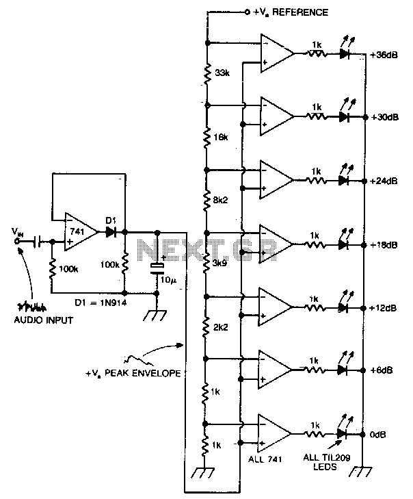
A vertical column of LEDs is configured so that as the audio signal level rises, an increasing number of LEDs illuminate. The LEDs are arranged in increments of 6 dB. The circuit features a fast response time and a...
This is an image Schematic. No Description available. The provided input indicates the existence of a schematic image without further descriptive content. In the context of electronic schematics, such images typically represent the arrangement and interconnection of various electronic...
The LM35 from National Semiconductor is a precision centigrade temperature sensor that provides an analog output voltage. It operates within a temperature range of -55°C to +150°C and has an accuracy of ±0.5°C. The output voltage corresponds to 10mV...
The experimenter's pot is a solid state potentiometer using Dallas semiconductor's DS1869 and National's LM78L05, two electrolytic capacitors, two small push button switches, and two optional Molex connectors. This project is very useful, especially in finding the right value...
This circuit is designed for precise centigrade temperature measurement. It features a transmitter section that converts the sensor's output voltage, which is proportional to the measured temperature, into frequency. The output frequency bursts are transmitted through the mains supply...