
8 MHz frequency meter using AVR microcontroller

The circuit for this project primarily consists of an AVR microcontroller, a clock source, and a display unit. The microcontroller is programmed to count the number of clock pulses received at its Timer input over a specified interval, in this case, one second.
The clock source can be any signal generator or oscillator that outputs a square wave signal, which serves as the input to the Timer. The Timer input pin of the microcontroller is configured to detect the rising or falling edges of the clock pulses, depending on the specific requirements of the application.
The Bascom code is responsible for initializing the Timer and configuring the necessary registers to enable counting. It sets up an interrupt or polling mechanism to capture the clock pulses accurately. After the counting period of one second, the code retrieves the count value from the Timer register and sends it to a display unit, which can be an LCD or LED display.
The display unit is connected to the microcontroller through appropriate data and control lines, allowing it to present the counted value in a readable format. The entire system is powered by a suitable power supply, ensuring that all components operate within their specified voltage and current ratings.
In summary, this project combines microcontroller programming, hardware interfacing, and display technology to create a functional clock pulse measurement system.This project can measure the clock pulses fed to the Timer input of the AVR microcontroller. The Bascom code counts the clock pulses for 1 second and display it. 🔗 External reference
Related Circuits
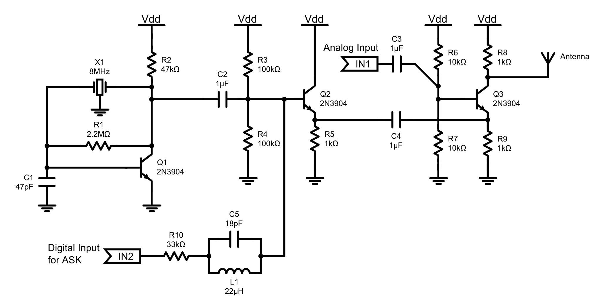
This is an 8MHz amplitude modulated (AM) radio transmitter designed primarily for work purposes and as an exercise in electronics. It serves as a simple radio transceiver that may be utilized for various future projects. The 8MHz AM radio transmitter...
The following circuit enables measurement of the inductance of the inductor labeled LX, which is the inductance to be measured. The output of the circuit is a TTL square wave whose frequency relates to the inductance being measured. The...
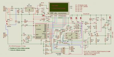
The following circuit illustrates a 40 MHz/400 MHz Frequency Counter Circuit Diagram. This circuit is based on the PIC16F84 IC. Features: The frequency counter circuit operates within the range of 40 MHz to 400 MHz, utilizing the PIC16F84 microcontroller...
The purpose of this project is to build a simple receiver for 50MHz. The receiver is built around the circuit MC3372, which is a narrow band FM receiver. The receiving frequency can be set with an LC tank or...

This is a simple siren sound generator with high power output and significant noise levels. The circuit utilizes digital integrated circuits (ICs), specifically the CD4046, in an inverter configuration along with four transistors to increase the current output to...
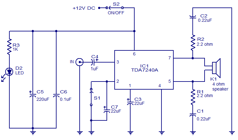
The audio amplifier presented here is based on the TDA7240 integrated circuit from ST Microelectronics. The TDA7240 is capable of delivering 20 watts of audio output power into a 4-ohm load. It requires a minimal number of external components...