
Inductance adapter for frequency meter

This circuit is designed for measuring inductance by utilizing a Colpitts oscillator configuration. The oscillator consists of a combination of an inductor (LX) and capacitors (four 1000pF capacitors) that create a resonant frequency dependent on the inductance. The output of the oscillator is a sine wave that is subsequently amplified by a transistor stage. The second transistor amplifies the sine wave to ensure that it is strong enough for further processing.
Following amplification, the sine wave undergoes rectification through a diode-capacitor arrangement, converting the AC signal into a pulsating DC signal. This rectified signal, which now only contains positive voltage excursions, is then buffered by a third transistor to provide a stable output for the next stage.
The buffered signal is fed into a 74LS393 counter IC, which is configured to divide the frequency by 256. This division is crucial as it allows for easier measurement and interpretation of the frequency output. The output from pin 6 of the IC is then connected to a frequency meter, which displays the frequency corresponding to the inductance being measured.
Powering the circuit is a 9V battery, which supplies voltage to the 7805 voltage regulator, ensuring that the IC and transistors receive a stable 5V supply. The use of a high-frequency transistor, such as the 2SC9018, is essential due to the nature of the signal being processed; alternatives can be used if necessary, but they must meet the frequency requirements of the circuit.
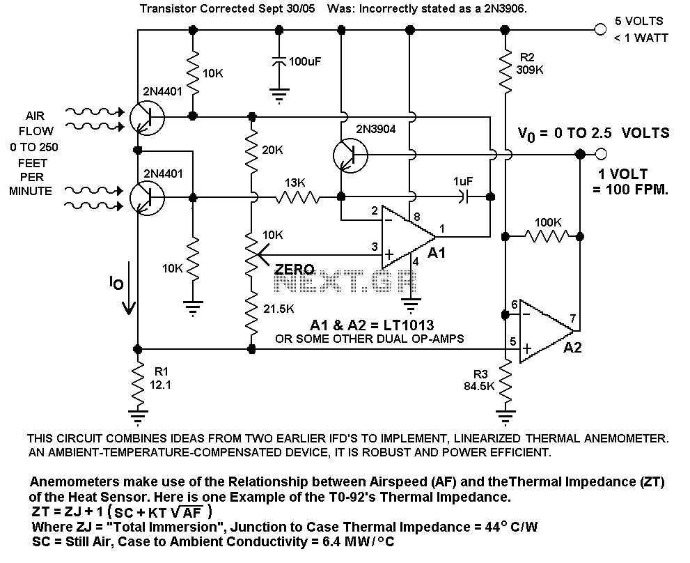
Overall, this inductance measurement circuit is a practical implementation for measuring inductance values using frequency as a reference, allowing for precise calculations based on the output frequency displayed on the frequency meter.The following circuit enables me to measure inductance of the inductor labeled LX which is the inductance to be measured. The o/p of the circuit is a TTL square wave whose frequency relates to the inductance being measured.
The heart of the circuit is the buffer colpitts oscillator(the first stage) which resonates with the unknown inductance to give a Sine wave of a particular frequency. The frequency of the sine wave is a function of the unknown inductance and the four 1000pF capacitors.
The output sine wave is amplified by the second transistor and is then rectified by the capacitor and diode combination that Follows. The rectified sine wave now having only positive excursions is buffered by the third transistor and is then fed to the 74ls393 Counter ic which is configured as a divide by 256 counter.
The output of the ic pin 6 and ground is connected to the frequency meter. The inductance meter adapter output is connected to a frequency meter and the inductance is calculated from the frequency.Hence you need a frequency meter and some calculation to get your inductor value. All resistances are in ohms. 7805 positive regulator 5v o/p. 2SC9018 is a high frequency transistor with FT of 1.1 Ghz . you need high frequency transistors in the circuit where it is used in case you want to substitute for it.
I guess 2n2857, 2n5179 ,BF180 can be substituted. The 7805 regulator powers the IC and the last 2 transistors. The circuit operates from a 9V battery which also feeds the regulator. The Ic consists of two counters in one package of 14 pins hence you need just one. PIN 14 is VCC and PIN 7 is ground. The ic is TTl IC 🔗 External reference
Related Circuits
I designed up this circuit board because of a request from a visitor to my website. I also assemble the circuit board to verify the board was correct. It does work, very nicely, but I have no way to...
This is a 7-digit frequency meter measuring frequency from 10 Hz up to 1300 MHz. It is based on ideas of PIC16F84 based frequency meter. The measuring range is divided into two subranges: 10Hz - 25MHz and 25 MHz...
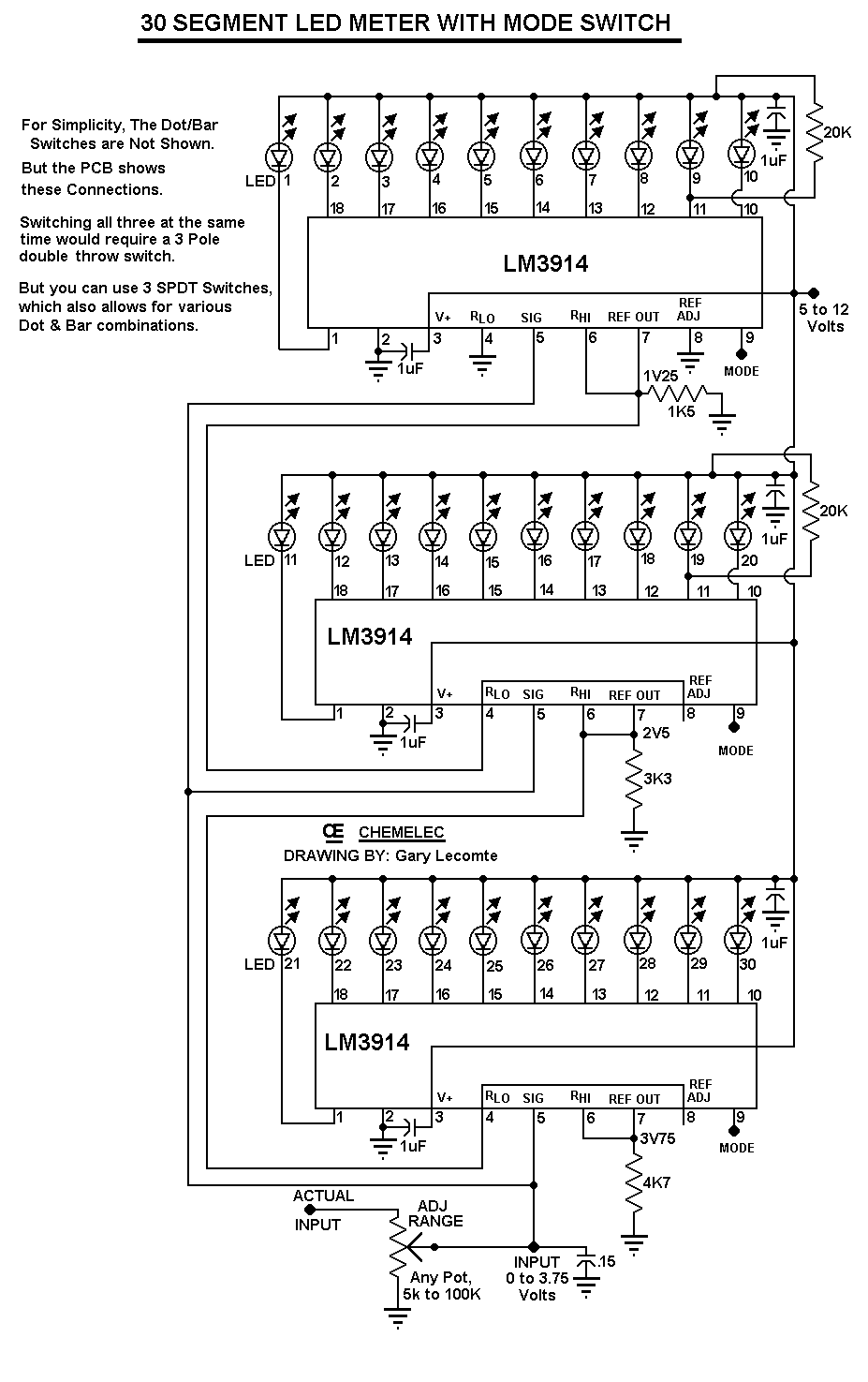
The circuit can be easily configured for full-scale voltages of either 20 or 200 volts by utilizing a suitable potentiometer on the input. It is critical not to exceed 30 volts at pin 5 of the LM3914. A 20...
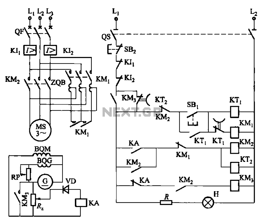
The circuit depicted in Figure 3-187 illustrates the operation of an auto step-down transformer (ZQB). Upon activation, the ZQB transformer initiates a sequence that allows the motor to gradually increase its speed. After a predetermined delay, the ZQB ceases...

Frequency converter schematic, frequency to voltage converter schematic, frequency to voltage converter using TR, voltage to frequency converter application. A frequency converter is an essential electronic circuit that transforms frequency signals into corresponding voltage levels or vice versa. The frequency...
Ultrasonic cleaning primarily relies on the phenomenon of ultrasonic cavitation. In the presence of a sound field, liquid bubbles undergo high-frequency micro-vibrations. When the sound pressure reaches a specific threshold, air bubbles grow rapidly and then collapse suddenly, creating...