
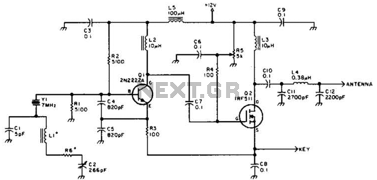
8MHz AM radio transmitter

The 8MHz AM radio transmitter operates by modulating the amplitude of a carrier wave at a frequency of 8 MHz. The transmitter circuit typically includes several key components: an oscillator, a modulator, an amplifier, and an antenna.
The oscillator generates a stable 8 MHz signal using a crystal or LC circuit, ensuring that the carrier frequency remains consistent. The modulator combines the audio input signal—often originating from a microphone or audio source—with the carrier wave. This process alters the amplitude of the carrier signal in accordance with the audio input, effectively encoding the sound information onto the radio wave.
The amplified output is then fed to the antenna, which radiates the modulated signal into the surrounding environment. The design may incorporate a low-pass filter to eliminate unwanted harmonics and improve the quality of the transmitted signal.
To ensure proper operation, power supply considerations are essential, typically involving a regulated DC source that provides the necessary voltage and current to the circuit. Additionally, components such as resistors, capacitors, and inductors may be included to stabilize the circuit and optimize performance.
This AM transmitter can be utilized for various applications, such as short-range communication, educational projects, or hobbyist experimentation, making it a versatile tool for electronics enthusiasts. Proper tuning and testing are crucial to achieving the desired transmission range and audio clarity.This is an 8MHz amplitude modulated (AM) radio transmitter, which I built mainly for work, and also as an exercise in electronics (it is the first RF transmitter I`ve ever built). We wanted to have a simple radio transceiver design at our disposal for some possible projects in the future that might require.
🔗 External reference
Related Circuits
A DSB transmitter is significantly less expensive to construct compared to an SSB transmitter since it does not require filters or phasing networks. This circuit can generate an output of up to 1 watt on the 10-meter band. The...
The circuit presented here represents one half of a device that is highly useful for tracing electrical wiring paths in buildings or locating breaks in wires. This system is based on equipment commonly used by technicians in telephone exchanges....
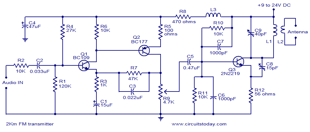
With a matching antenna, the FM transmitter circuit can transmit signals over a range of 2 kilometers. The transistors Q1 and Q2 form a highly sensitive preamplifier stage. The audio signal to be transmitted is coupled to the base...

This circuit enables the use of a portable VHF FM radio to receive audio from stations that exclusively broadcast on the local cable network. This circuit operates by modulating the audio signals from the local cable network onto a carrier...
A Tesla Coil can be understood as a high-power radio frequency transmitter with an inefficient antenna. The secondary coil functions as a significantly shortened quarter-wave antenna. The Tesla Coil is an electrical resonant transformer circuit that is designed to produce...
Construct a low-power FM transmitter using surface-mount devices (SMD) that can be received by a standard FM radio. The proposed low-power FM transmitter circuit utilizes surface-mount devices (SMD) to achieve compactness and efficiency. The primary components of the circuit include...