
Three-way operation of the dynamic braking circuit

The circuit utilizes a time relay, which is a crucial component for controlling the duration of the braking process. The time relay KT is designed to introduce a specific delay before the braking action is initiated. This delay can be adjusted based on the requirements of the application, allowing for flexibility in operation.
In the circuit, the input signal activates the time relay, which then begins its timing sequence. Once the preset time elapses, the relay contacts close, triggering the braking mechanism. The relay's timing can be set using variable resistors or capacitors, depending on the design, enabling precise control over the braking duration.
The overall functionality of the circuit is essential in applications where controlled deceleration is necessary, such as in motor control systems or automated machinery. By regulating the braking time, the circuit helps prevent mechanical stress and enhances safety during operation. Proper selection of the time relay's specifications, such as its voltage rating and timing range, is vital for ensuring reliable performance in the intended application. Circuit shown in Figure 3-135. Braking time is determined by the time relay KT.
Related Circuits

This circuit generates a siren sound when switch S1 is pressed. The sound frequency increases as capacitor C1 charges, and when switch S1 is released, the frequency decreases as capacitor C1 discharges. The circuit operates on a simple principle of...
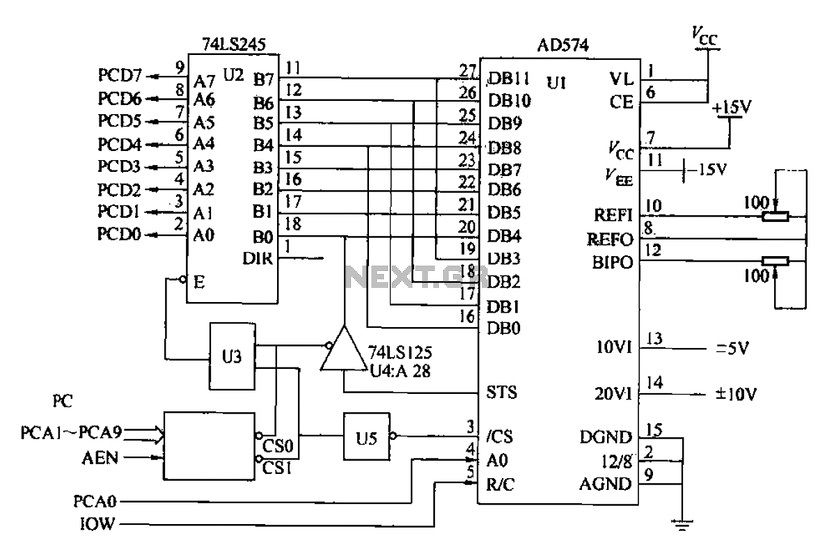
Another example is provided using the AD574 and PC bus. The AD574 converter is represented by U1, while U2 is a 74LS245 bidirectional data buffer. U3 is a 74LS00 two-input AND gate, U4 is a 74LS125 tri-state output gate,...
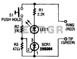
Section Ul-a is configured as a high-gain inverting voltage amplifier that is inductively coupled to the phone line via LI. Inductor LI is a homemade unit that consists of 250 turns of fine, enamel-coated wire that is wound on...
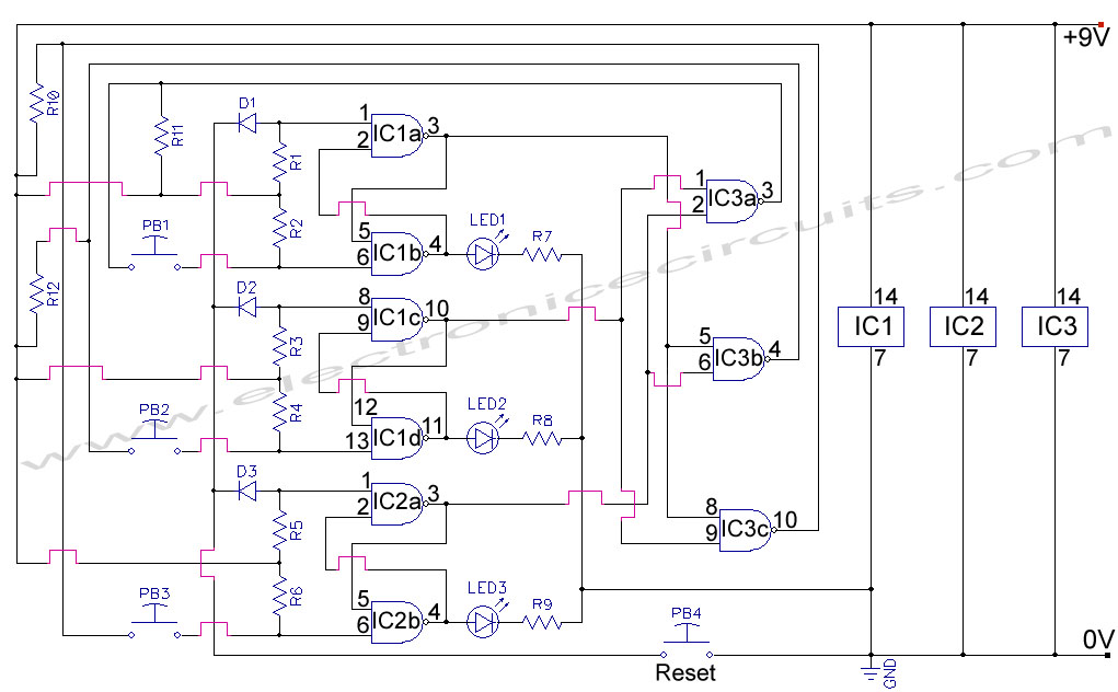
First Response Monitor, Input Selector, Game Circuit. This circuit is utilized for first response applications as it aids in monitoring various responses in games. The First Response Monitor circuit is designed to facilitate real-time monitoring and selection of input signals...
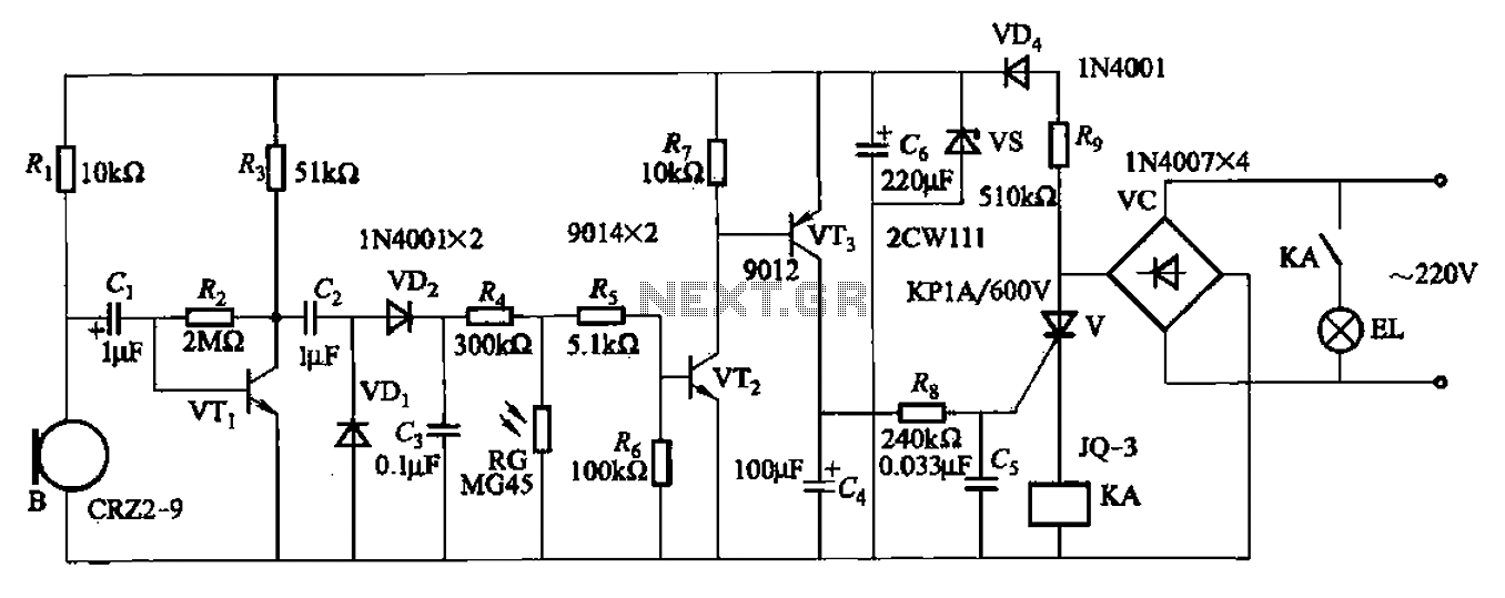
A resistor R8, capacitors Cd, and a thyristor V AC switch form a delay circuit. The lamp's lighting delay time is determined by the resistor Rs and capacitor C4, with a delay of approximately 40 seconds as indicated in...
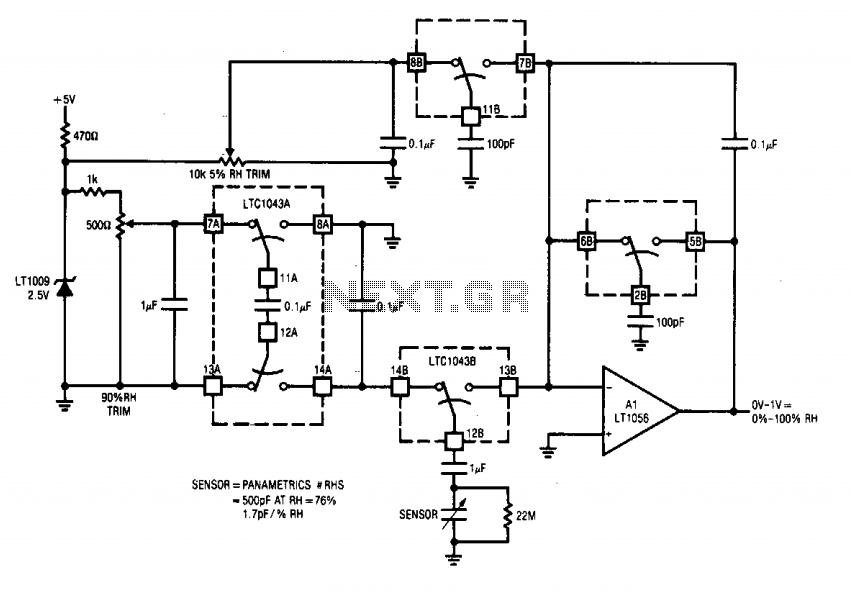
This circuit integrates two LTC1043 devices with a humidity transducer based on a charge-pump configuration. The specified sensor has a nominal capacitance of 400 pF at a relative humidity (RH) of 76%, exhibiting a slope of 1.7 pF/% RH....