
Camera Switcher

The described circuit functions as a video switching system, enabling the connection of multiple camera inputs to a single monitor output. This configuration is particularly useful in surveillance applications, where multiple camera feeds need to be monitored simultaneously or switched between as required.
The circuit typically includes a selection mechanism, which can be implemented using either mechanical switches for manual operation or electronic components such as relays or transistors for automatic operation. In a manual setup, a rotary switch or push-button switches allow the user to select which camera feed is displayed on the monitor. In an automatic configuration, a microcontroller or timer circuit can be employed to cycle through the camera feeds at predetermined intervals or based on specific triggers, such as motion detection.
Key components of the circuit may include:
- **Cameras**: Each camera should be compatible with the chosen video format (e.g., NTSC, PAL) and have the necessary power supply.
- **Multiplexer or Switch**: A video multiplexer can be used to handle multiple video inputs, allowing for seamless switching between feeds. Alternatively, analog switches or relays can be used for simpler applications.
- **Monitor**: A single video monitor capable of displaying the output from the selected camera. The monitor should support the video format being used.
- **Control Logic**: For automatic operation, a microcontroller (e.g., Arduino, Raspberry Pi) can be programmed to manage the switching logic, controlling the multiplexer or switch based on predefined criteria.
Power supply considerations are crucial, as adequate voltage and current must be supplied to all cameras and active components. Signal integrity should also be maintained, requiring the use of appropriate cabling and connectors to minimize interference and ensure high-quality video transmission.
Overall, the circuit’s design should prioritize user-friendliness and reliability, ensuring that the switching mechanism functions smoothly whether operated manually or automatically.This circuit can be used for multiple cameras with one monitor. The circuit can be operated manually or automatically. 🔗 External reference
Related Circuits

The prototype circuit board utilized an external LCD display that received commands through an RS-232 interface. While this setup functioned adequately, programming it was cumbersome. Consequently, the circuit board was revised to support a directly attached LCD display. The...

The transistor Q1 remains off until the magnetic switch connected to J1 closes. When this occurs, 9V is supplied through R1 to the base of Q1. As a result, Q1 turns on, which charges capacitor C2 through relay K1,...
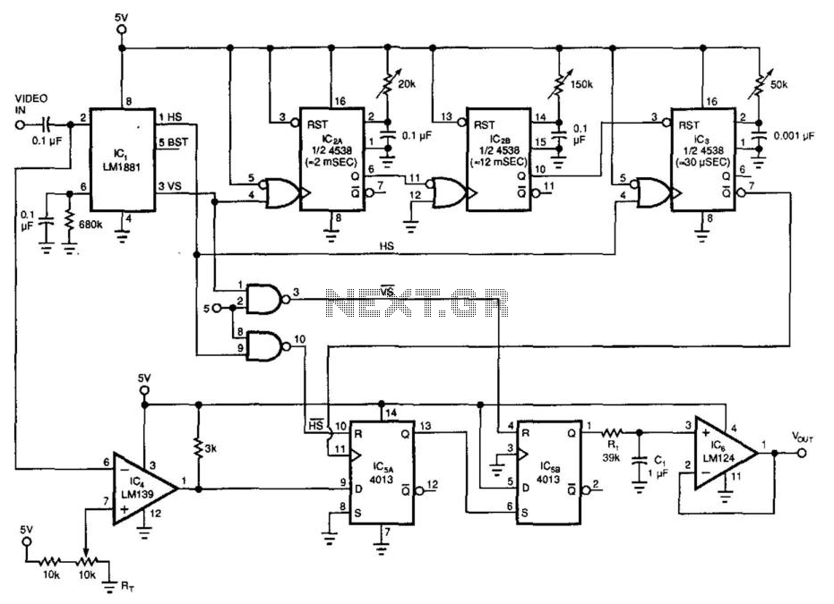
By utilizing a low-cost RS-170 camera and this circuit, a voltage that indicates the position of an object within the camera's field of view is generated. IC2A and IC2B create a valid video gate that keeps IC3 in a...
The aim of this project was to get a digital camera into a small electric radio controlled (RC) aeroplane and still have it fly. The aeroplane shown, a park flyer, weighs between 400 and 550 grams depending on the...
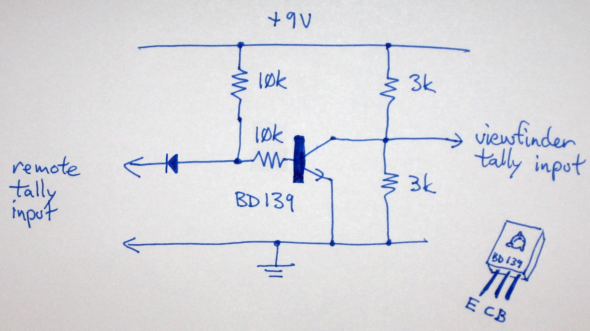
Instructions for enabling the tally light on the F15 camera viewfinder without access to the CCU/RCU. To activate the tally light on an F15 camera viewfinder in the absence of a Camera Control Unit (CCU) or Remote Control Unit (RCU),...
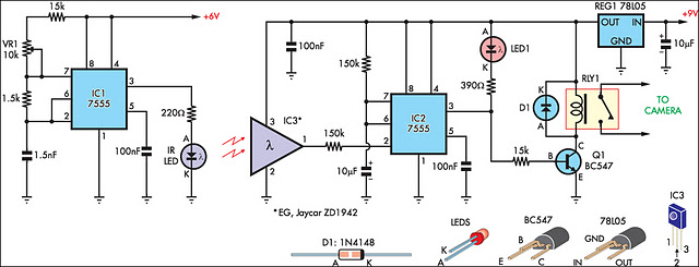
This circuit serves as an alternative to the infrared (IR) beam break detector featured in the June 2009 issue of Silicon Chip. To enhance its insensitivity to ambient light, it employs a standard IR receiver integrated circuit (IC), such...