
Three Channel Audio Mixer Circuit
The Mini Mixer is designed to cater to users who require a compact and efficient solution for mono signal mixing. The three input channels facilitate the connection of various audio sources, such as microphones or musical instruments. Each input is equipped with a sensitivity switch that allows the user to select between high and low sensitivity modes, accommodating a range of signal levels and ensuring optimal performance regardless of the source.
The unique level-control circuits employed in this design are engineered to provide a high degree of linearity and stability, which is crucial for maintaining audio quality during mixing. This design minimizes distortion and noise, resulting in a clean output signal. The proportionality of noise levels to gain settings is particularly advantageous, as it allows users to adjust the mix without introducing unwanted artifacts.
The five-transistor configuration is a key element of the Mini Mixer's low current consumption. By utilizing a minimal number of components, the design achieves efficiency while maintaining functionality. This makes the Mini Mixer an ideal choice for portable applications, as it can be powered by a common 9V PP3 battery, offering extended operational life suitable for field use or mobile setups.
Overall, the Mini Mixer stands as a practical solution for users seeking a straightforward, reliable, and efficient mixer for mono signals, combining user-friendly features with robust performance in a compact format.Although the modular Portable Mixer design available on these web pages has become a hit for many amateurs, some correspondents required a much simpler device, mainly for mixing mono signals. This design should fulfil their needs, featuring three inputs with switchable high/low sensitivity and unusual level-control circuits, providing high overload margins and low-noise figures, proportional to gain-level settings.
Low current consumption due to a simple, five-transistor circuitry, allows the Mini Mixer to be powered by a common 9V PP3 battery for many hours.. 🔗 External reference
Related Circuits
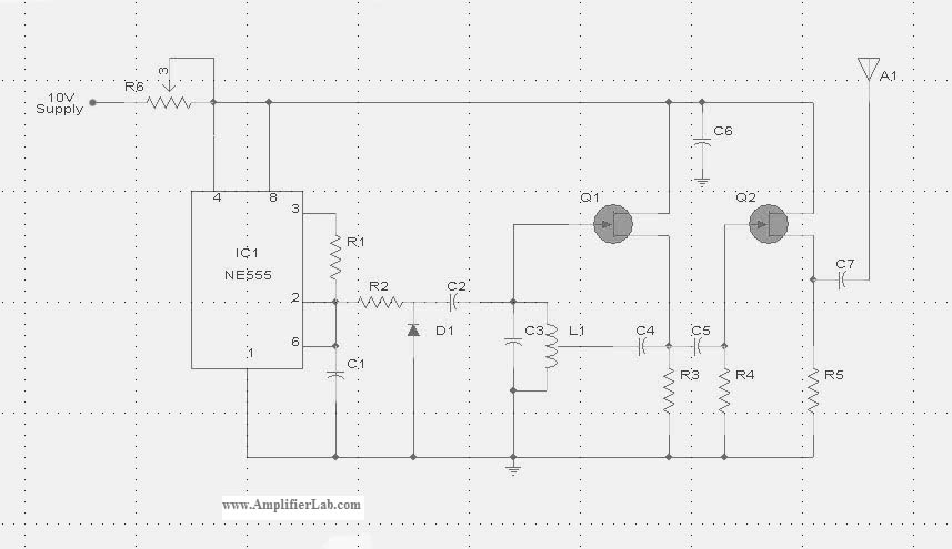
The circuit diagram of the Radio Collar Transmitter is presented here. This circuit is based on the NE555 integrated circuit, which serves as the central component. The Radio Collar Transmitter circuit utilizes the NE555 timer IC to generate a modulated...
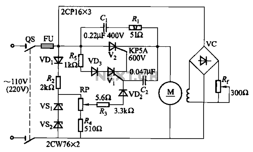
A 100W resistance-triggered motor control circuit designed for arc welding machines. It features an adjustment potentiometer (Rr) that can modify the DC motor excitation current. Additionally, a regulator (RP) is included to adjust the DC motor armature voltage, enabling...
Standard LED flashers activate the LED in a rapid on-off sequence, which can become bothersome over time. The circuit presented here offers a more gradual illumination effect. This circuit utilizes a simple design to create a soft flashing LED effect,...
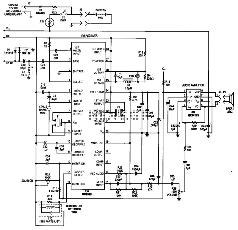
Using a Motorola MC3363 LSI one-chip FM receiver, the circuit is a dual-conversion FM receiver with a 10.7-MHz IF chain. IC4 provides power to drive a small speaker. The described circuit employs the Motorola MC3363 integrated circuit, which is designed...
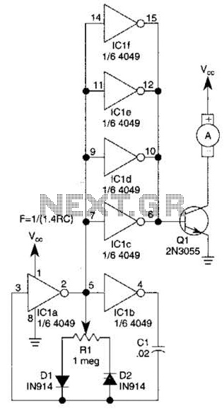
This circuit will drive a small DC motor over a wide range of speeds without stalling by controlling the duty cycle of the motor, rather than the supply voltage. The described circuit utilizes pulse width modulation (PWM) to effectively control...
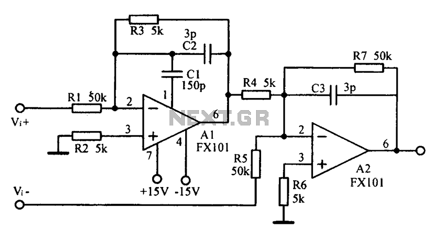
Common mode input voltage up to a difference of 100V enlarged circuit diagram. The circuit diagram described features a design capable of handling a common mode input voltage with a differential range of up to 100V. Such a configuration is...
Warning: include(partials/cookie-banner.php): Failed to open stream: Permission denied in /var/www/html/nextgr/view-circuit.php on line 713
Warning: include(): Failed opening 'partials/cookie-banner.php' for inclusion (include_path='.:/usr/share/php') in /var/www/html/nextgr/view-circuit.php on line 713