
simple 100 watt inverter

The circuit design for this 100-watt inverter is straightforward, relying on the astable multivibrator configuration of the CD4047 IC to produce a square wave signal. The frequency of 100Hz is suitable for driving the transformer, allowing the inverter to convert the low-voltage DC input into a usable AC output. The use of the CD4047 as a frequency generator is advantageous due to its reliability and ease of integration into the circuit.
The amplification stage, consisting of the TIP122 and 2N3055 transistors, is critical for ensuring that the output signal is strong enough to drive the transformer effectively. The TIP122, a Darlington pair transistor, provides high current gain, which is essential for driving the larger 2N3055 power transistors. The configuration of using two 2N3055 transistors in parallel for each half of the output cycle helps distribute the load and prevent overheating, thereby enhancing the overall efficiency and reliability of the inverter.
The choice of transformer is also crucial; using a 12V-0-12V transformer in reverse allows for a significant voltage increase, enabling the inverter to provide 220V AC output. The transformer must be rated appropriately to handle the desired output power without saturating. For applications requiring less power, a 5A transformer can suffice, but it is important to note that this will limit the inverter's output capacity to 60 watts.
Overall, this inverter circuit is an efficient solution for small power applications, providing a simple yet effective means of converting DC to AC power for various household devices.This is a simplest circuit for 100 watt inverter for generating 220vAC from 12vDC. I say simplest because here in this inverter circuit a minimum number of components are used to design the schematic, which is quite difficult to make a circuit like this with further fewer components. This 100W inverter circuit works great for small loads like a fa n or 2-3 bulbs/lamps. In this circuit as IC1 we used a CD 4047 IC to generate 100Hz frequency (180 degree out of phase). CD 4047 IC is from Texas Instruments. It is mostly used as Astable/Monostable signal generator device. In this circuit it is triggered as astable multivibrator by the capacitor C1 between the Pin 1 and 3 of CD4047. And VR1 is used to adjust the frequency of signal. Four 2N3055 transistors are used to amplify the pulse trains that are pre-amplified by two TIP122 transistors.
There used three transistors for each side (half cycle), one TIP122 & two 2N3055 transistor to drive the output transformer (TX in circuit). Four 2N3055 transistors are used as driving transistor. An inverters maximum output power depends on two factors; one is the max current rating of transformer`s primary winding and other factor is the current rating of driver transistors.
Transformer: Use a 12v-0-12v, 10A step-down transformer in reverse. That`s mean secondary winding (12v-0-12v) will be the primary and primary winding (220VAC side) will be the secondary (output). So that it will worked like a step-up transformer. You can also use a 5A transformer instead of 10A, if you couldn`t have 10A. But the output power will decrease to 60 Watt. 🔗 External reference
Related Circuits
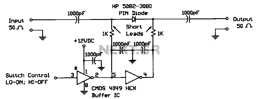
When the digital logic level at the control input is low, the PIN diode is forward-biased by the CMOS gates. The two 1-KΩ bias resistors limit this current to the PIN diode's safe forward current limit. In this state,...

The diagram illustrates a simple and efficient receiver designed for controlling garage doors, starter motors, alarms, warning systems, and various other applications. The SCR utilized in this circuit features an exceptionally low trigger current of 30 µA. The circuit operates...

This circuit is a simple series tone control circuit utilizing the OP-Amp LM301A. The JFET 2N3684 provides high input impedance and low noise characteristics for the feedback buffer in the op-amp-based tone control. The tone control circuit described employs an...
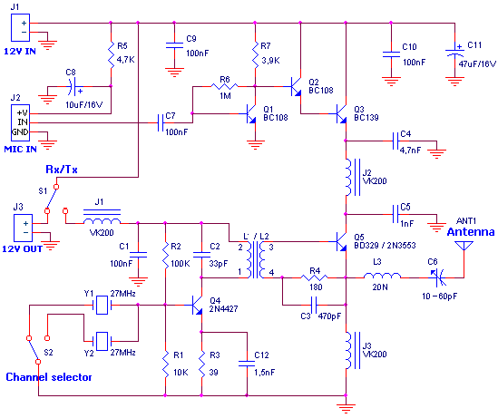
For the regulation it needs a voltmeter (with needle better) and charge 50W/5W. Connect charge 50W in the place of aerial, with the voltmeter in the exit voltmeter. Be supplied the transmitter with + 12V. It will be supposed...
this is a very easy circuit to build - all parts can be found at the local electronics shop. The described circuit is characterized by its simplicity and accessibility, making it an ideal project for beginners or those looking to...
This is a circuit diagram for a fuse monitor circuit indicator. This very simple circuit utilizes only two components: a single resistor and an LED. This circuit provides a visual indication when the fuse has blown. LED1 typically remains...