
88-108 Mhz to AM broadcast band

This circuit serves as an interface between an FM tuner and an AM radio, allowing the reception of FM stations on an AM band. The design typically includes a modulator that converts the frequency of the FM signal into a format that can be transmitted over the AM band.
The circuit may consist of the following key components:
1. **FM Tuner**: The FM tuner receives the desired FM radio frequency. It often includes a front end that filters and amplifies the incoming signal to ensure clarity and strength.
2. **Modulator**: This component is crucial as it converts the FM signal into an AM signal. A common approach is to use a product modulator or a balanced modulator that mixes the FM signal with a carrier frequency, which is typically set within the AM band.
3. **Carrier Oscillator**: This oscillator generates the carrier frequency that the modulator uses. The frequency is adjustable, allowing the user to select a specific AM channel for transmission.
4. **Amplifier**: After modulation, the AM signal may require amplification to ensure it can be effectively transmitted over the airwaves. A Class C amplifier is often used for this purpose due to its efficiency in broadcasting.
5. **Antenna**: The output signal is then transmitted via an antenna designed for AM frequencies. This antenna should be carefully designed to match the impedance of the amplifier to maximize power transfer.
6. **Power Supply**: A stable power supply is necessary to provide the required voltage and current to the circuit components, ensuring reliable operation.
In summary, this circuit effectively bridges the gap between FM and AM radio technologies, enabling users to enjoy FM broadcasts on standard AM receivers. Proper tuning and alignment of the components are essential for optimal performance and signal quality.I designed this circuit. It can be connected to an FM tuner to play FM stations on an AM radio. 🔗 External reference
Related Circuits
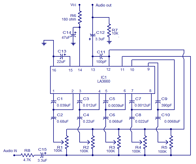
The graphic equalizer described is based on the LA3600 integrated circuit from Sanyo Semiconductors. The LA3600 is a single operational amplifier, 5-band graphic equalizer IC that is well-suited for applications such as portable stereo systems, radios, home theater systems,...

An RF power amplifier is an electronic amplifier used to convert a low-power radio-frequency signal into a larger signal of significant power, typically for driving the antenna of a transmitter. It is optimized for high efficiency, high output power...
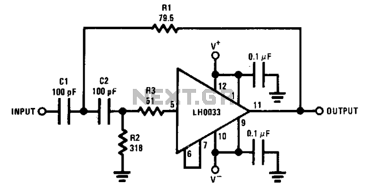
The circuit features a cutoff frequency of 10 MHz. Resistor R3 is utilized to prevent the input capacitance of the amplifier from affecting the filter response at the desired frequency. An equivalent low-pass filter can also be derived through...
In this circuit, a 74HC14 hex Schmitt trigger inverter functions as a square wave oscillator to drive a small signal transistor configured as a class C amplifier. The oscillator frequency can be set to a fixed value using a...
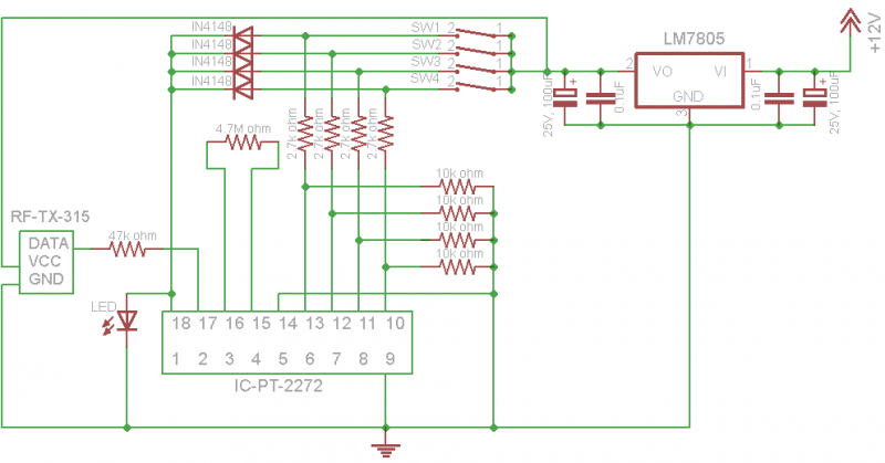
Decoder Tags: PT2262, PT2272, Remote Control, RF-RX-315, RF-TX-315. The RF remote control operates at a frequency of 315 MHz using an RF remote control encoder and decoder. Published by cl.chin on September 3, 2012. The RF-TX-315 and RF-RX-315 modules...
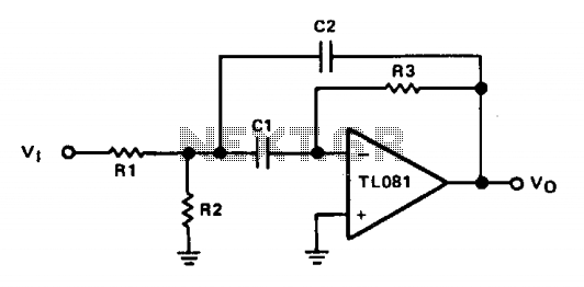
The operational amplifier (op amp) is configured in inverting mode. Resistor R3 connects the output to the inverting input, establishing the gain and the current through the frequency-determining capacitor, C1. Capacitor C2 provides feedback from the output to the...