
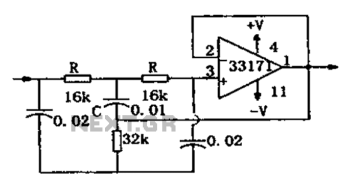
Wideband two-pole high-pass filter

The circuit is designed to implement a low-pass filter with a cutoff frequency of 10 MHz, which is critical for applications requiring signal conditioning and noise reduction. The primary function of the filter is to allow signals below this frequency to pass while attenuating higher frequency signals, thus ensuring the integrity of the desired signal.
Resistor R3 plays a pivotal role in the circuit by isolating the input capacitance of the amplifier from the filter's response. This isolation is crucial because any interaction between the amplifier's input capacitance and the filter could lead to unintended alterations in the filter's frequency response, potentially degrading the performance of the circuit. By carefully selecting the value of R3, the designer can ensure that the input capacitance does not introduce phase shifts or amplitude variations at the cutoff frequency.
The equivalent low-pass filter configuration can be achieved through the transformation of capacitance and resistance. This method allows for the design of filters with specific characteristics by altering the values of the components in the circuit. In practice, this means that a designer can tailor the filter's performance to meet specific application needs by adjusting the resistance and capacitance values accordingly.
Overall, the described circuit is a well-considered design that effectively utilizes resistor R3 to maintain filter integrity while providing the necessary low-pass filtering characteristics for signals in the 10 MHz range. The ability to transform component values further enhances the flexibility and adaptability of the circuit in various electronic applications.The circuit provides a 10MHz cutoff frequency. Resistor R3 ensures that the input capacitance of the amplifier does not interact with the filter response at the frequency of interest. An equivalent low pass filter is similarly obtained by capacitance and resistance transformation.
Related Circuits

This is a simple low pass filter that can be used at any audio circuitry. It uses the 741 opamp. More: Do not forget to use double power supply of 5 volts. You can use 2 batteries as shown...
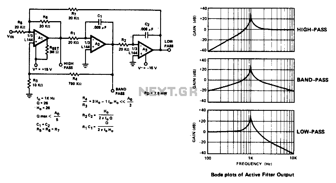
The active filter is a state variable filter with bandpass, high-pass, and low-pass outputs. It is a classical analog computer method of implementing a filter using three amplifiers and only two capacitors. The state variable filter is a versatile circuit...
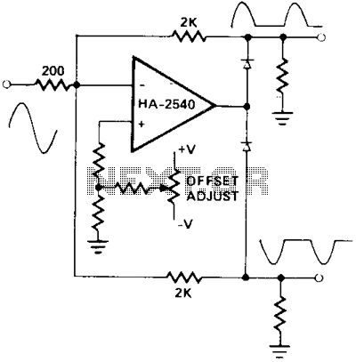
A circuit utilizing either the HA-2539 or HA-2540 in conjunction with two low-capacitance switching diodes can effectively separate signals exceeding 10 MHz. This configuration is particularly beneficial for applications such as full-wave rectification, AM detection, or synchronization generation. The described...
A current differencing transconductance amplifier (CDTA) serves as an active component that can be utilized to create various filter responses. The selection of different filter characteristics is achieved by altering the bias current supplied to the amplifier. The current differencing...
A schematic diagram for a broadband QRP SWR metering circuit intended for use in a QRP antenna tuner. The circuit allows the user to press a momentary DPDT switch to observe an LED indicator while adjusting the capacitors of...
The trap circuit utilizes a high-performance operational amplifier, MC33171, to create the trap. This device features a wide bandwidth and high conversion rate. The component values can be modified by adjusting the capacitance of capacitor C and the resistance...