
Automatic Light Switch Circuit

The light-sensitive automatic light switch circuit operates by utilizing a light-dependent resistor (LDR) to detect ambient light levels. When the light levels drop below a certain threshold, indicating nighttime, the LDR changes its resistance, allowing current to flow through the circuit. This triggers a relay or a transistor switch that connects the 220V supply to the lamp, turning it on.
The fundamental components of this circuit include the LDR, a resistor to form a voltage divider, a transistor or relay for switching, and a 220V lamp. The LDR is positioned in such a way that it is exposed to ambient light. In bright conditions, the LDR has low resistance, which keeps the transistor in the off state, thus preventing the lamp from lighting up. As darkness falls, the resistance of the LDR increases, leading to a voltage change across the resistor that activates the transistor or relay.
To ensure safe operation, the circuit should include necessary protective components such as fuses or circuit breakers to prevent overloads. Additionally, the circuit can be enhanced with a delay mechanism to prevent the lamp from turning on due to brief fluctuations in light levels, such as passing clouds.
This automatic light switch circuit is particularly useful for outdoor lighting, garden lights, or any application where automatic control of lighting based on ambient light conditions is desired. Proper insulation and adherence to electrical safety standards are essential when working with high-voltage circuits to ensure safety and reliability.This light sensitive automatic light switch circuit is intended to be connected at the main 220V supply. The circuit will connect a 220V lamp at the nightf.. 🔗 External reference
Related Circuits
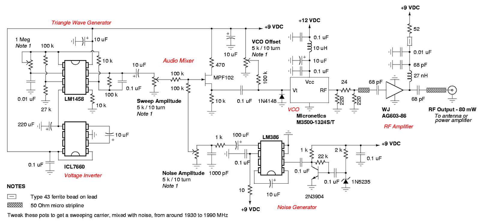
An admirable DIY GSM jammer or cellular mobile phone jammer schematic diagram designed for use with GSM1900, operating within the frequency range of 1930 MHz to 1990 MHz. The GSM1900 cellular mobile phone system is utilized in the USA,...
This article compares high-side and low-side amplifiers used for measuring battery charging currents. It recommends selection criteria for current-sense resistors and describes a high-voltage circuit breaker designed for overcurrent protection. High-side and low-side amplifiers are essential components in battery management...
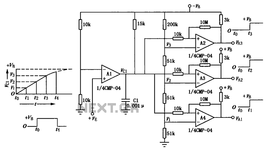
A multi-stage delay circuit is presented in this schematic. The operational amplifiers are configured as comparators. Operational amplifier A1 operates when the voltage at the inverting input exceeds + VE. As the voltage at the inverting input of operational...
This circuit diagram illustrates the conversion of a speaker into a microphone. When sound waves impact the diaphragm of a speaker, fluctuations occur in the coil, generating an induced voltage. This induced voltage is typically substantial but low in...
2000 Plymouth Breeze Dash Light Wiring Diagram. The 2000 Plymouth Breeze dash light wiring diagram provides a detailed overview of the electrical connections and components associated with the vehicle's dashboard lighting system. This diagram serves as a crucial reference for...
The purpose of this timer is to disconnect the compressor circuit and connect a resistive heating element located near the evaporator at regular time intervals. The defrost heater is controlled by a thermostat and is used to melt any...