
9 LED VU meter

The circuit described is a 5 LED VU Meter utilizing the LB1409 integrated circuit from SANYO, designed to visually represent the amplitude of an audio signal. The circuit operates with a supply voltage of 12V DC and consumes approximately 50mA of current.
The LB1409 IC serves as the core component, which processes the incoming audio signal and drives the LEDs accordingly. The circuit includes two potentiometers: PR1, which is used to set the reference level, and PR2, which adjusts the sensitivity of the audio input.
When an audio signal is applied, the LB1409 analyzes the signal's amplitude and activates the corresponding number of LEDs based on the detected volume level. The first LED lights up at the lowest volume threshold, with each subsequent LED illuminating as the volume increases, providing a clear visual indication of the audio level.
To construct this circuit, the following components are necessary:
- LB1409 IC
- Five LEDs (preferably of the same color for uniformity)
- Two potentiometers (PR1 and PR2)
- Resistors to limit the current through the LEDs
- A power supply capable of providing 12V DC
- Additional passive components such as capacitors for smoothing and filtering the audio signal as needed.
The layout should ensure that the audio input is connected to the appropriate pins of the LB1409, and the output pins are connected to each of the LEDs through current-limiting resistors. Proper grounding and decoupling capacitors should be placed near the power supply pins of the IC to ensure stable operation.
This circuit can be used in various audio applications, including amplifiers and mixers, to provide a visual representation of audio levels, aiding in sound engineering and mixing tasks.This simple and easy to make circuit is a 5 LED VU Meter based on LB1409 IC from SANYO, which will indicates the volume level of the audio signal it senses. SUPPLY 12V DC @ 50mA. PR1 REF SET. PR2 AUDIO LEVEL SET 🔗 External reference
Related Circuits

Each step will result in a self-functional unit. By the end of this process, it will be possible to link the steps together into a powerful FM transmitter. This section will explain the main controlling unit for the FM...
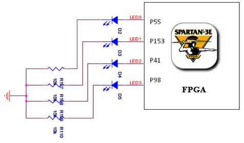
The Spartan-3E board features four LEDs connected to FPGA I/O pins, as detailed in the accompanying table. Each LED's cathode is connected to ground through a 330-ohm resistor. To illuminate a specific LED, the corresponding FPGA control signal must...

This is a nice example circuit that can be used at parties. The four LEDs blink to the beat of the music. The light organ using a microphone responds to sound. T1 amplifies the signal from MIC. The sensitivity...
This circuit uses the effect of a FET as the power to act through the gate with the source to connect. The voltage may vary between 4V and 30V, the current through the LED should constantly be around 15mA....
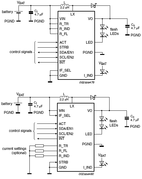
This device offers an extended battery life and operates with low power consumption. Additional features include battery and LED overload protection, seamless operation with safeguards against overtemperature, overvoltage, a timeout function, undervoltage lockout, and feedback short-circuit protection. The device is...

A Multi Switch Controlled Relay circuit is utilized to manage home appliances, featuring a circuit diagram that outlines the application of a multi switch-controlled relay using a single integrated circuit (IC) for various control functions. The Multi Switch Controlled Relay...