
9-Line Telephone Sharer

The circuit design employs a robust architecture to facilitate seamless communication across multiple extensions while preserving privacy. The use of an opto-coupler (MCT-2E) allows for electrical isolation, enhancing safety and reliability by preventing high voltages from affecting the low-voltage components. The 555 timer (IC2) is configured in monostable mode, providing a precise timing function to manage the call duration and ensure that the system operates within the defined 10-second window for dialing the extension.
The relay (RL10) serves a dual purpose: it powers the processing circuitry and interrupts the ringing signal to prevent unwanted interruptions. The integration of the tone receiver (CM8870) with the BCD decoder (CD4028) ensures that only the intended extension receives the ring signal, effectively eliminating the risk of cross-talk and ensuring that users can communicate without the fear of eavesdropping.
Relay RL1's activation connects the 50Hz ringing signal to the designated telephone line, ensuring that only the intended recipient is alerted to the incoming call. The design cleverly uses a diode (D1) and a DIAC (DIAC1) to create a voltage threshold that prevents other extensions from receiving the ringing signal, further enhancing the privacy aspect of the circuit. Overall, the schematic provides a sophisticated solution for managing multiple telephone extensions efficiently while maintaining user confidentiality.This circuit is able to handle nine independent telephones (using a single telephone line pair) located at nine different locations, say, up to a distance of 100m from each other, for receiving and making outgoing calls, while maintaining conversation secrecy. This circuit is useful when a single telephone line is to be shared by more members resi ding in different rooms/apartments. Normally, if one connects nine phones in parallel, ring signals are heard in all the nine telephones (it is also possible that the phones will not work due to higher load), and out of nine persons eight will find that the call is not for them. Further, one can overhear others` conversation, which is not desirable. To overcome these problems, the circuit given here proves beneficial, as the ring is heard only in the desired extension, say, extension number 1`.
For making use of this facility, the calling subscriber is required to initially dial the normal phone number of the called subscriber. When the call is established, no ring-back tone is heard by the calling party. The calling subscriber has then to press the asterik (*) button on the telephone to activate the tone mode (if the phone normally works in dial mode) and dial extension number, say, 1`, within 10 seconds.
(In case the calling subscriber fails to dial the required extension number within 10 seconds, the line will be disconnected automatically. ) Also, if the dialed extension phone is not lifted within 10 seconds, the ring-back tone will cease.
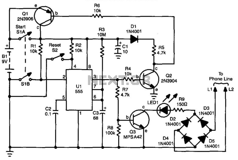
The ring signal on the main phone line is detected by opto-coupler MCT- 2E (IC1), which in turn activates the 10-second on timer`, formed by IC2 (555), and energises relay RL10 (6V, 100- ohm, 2 C/O). One of the N/O` contacts of the relay has been used to connect +6V rail to the processing circuitry and the other has been used to provide 220-ohm loop resistance to deenergise the ringer relay in telephone exchange, to cut off the ring.
When the caller dials the extension number (say, 1`) in tone mode, tone receiver CM8870 (IC3) outputs code 0001`, which is fed to the 4- bit BCD-to-10 line decimal decoder IC4 (CD4028). The output of IC4 at its output pin 14 (Q1) goes high and switches on the SCR (TH-1) and associated relay RL1.
Relay RL1, in turn, connects, via its N/O contacts, the 50Hz extension ring signal, derived from the 230V AC mains, to the line of telephone 1`. This ring signal is available to telephone 1` only, because half of the signal is blocked by diode D1 and DIAC1 (which do not conduct below 35 volts).
🔗 External reference
Related Circuits
FM Telephone Bug. This is a simple transmitter that, when connected to a phone line, will transmit any audio on that line (except the dial tone) to any FM radio. The FM Telephone Bug is designed to intercept and transmit...
This circuit operates as a line-current sensor and can be connected in series with any of the phone lines. To indicate an "in use" status for all phones on a single line, it must be connected in series with...
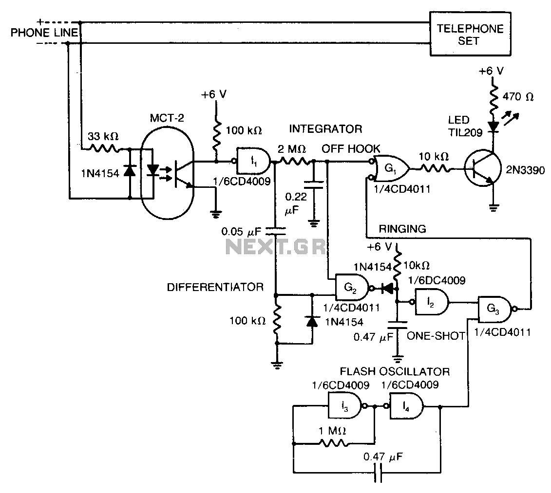
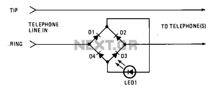
The LED signifies the status of a remote telephone. The light remains off when the phone is hung up. It emits a steady glow when the phone is off the hook, and it flashes intermittently while the phone is...
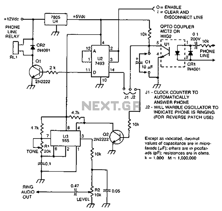
Check the loop circuit for an automatic telephone answering system or a tone generator for use in reverse automatic repair. The loop circuit in an automatic telephone answering system is designed to detect incoming calls and activate the answering mechanism....
If a user is busy and cannot answer or does not wish to answer their phone, this circuit will emit a busy signal without requiring the phone to be left off the hook. After a predetermined duration, the circuit...
The circuit described can connect two telephones in parallel and function as a two-line intercom. Typically, a single telephone is connected to a telephone line. When another telephone is needed at a distance, a parallel line is utilized for...