
9 V NiCd or NiMH accumulator charger

This circuit is a universal battery charger designed for 9V batteries, primarily NiCd and NiMH types, utilizing a constant current source for charging. The charger operates with a supply voltage range of 15-25 V DC or 12-20 V AC, allowing versatility in power source selection. It incorporates a current regulation system utilizing transistors T1 and T2, which maintain a charging current typically set around 15 mA, adjustable as per requirements.
The charging process is indicated by a red LED (LED1), which remains lit during charging. Once the charging period is completed, the LED turns off, and a secondary green LED (LED2) blinks to indicate that the timer circuit has completed its cycle. The timer is managed by a HEF4541 integrated circuit, configured as an RC oscillator and binary divider. The oscillator operates at a frequency of approximately 0.7 Hz, determined by the resistor R6 and capacitor C2, producing a pulse that signifies the end of the charging cycle after about 13.5 hours.
The circuit includes additional components such as a diode (D1) for power supply regulation, and a zener diode (ZD) to stabilize the voltage for the timer circuit. The average charging current is calculated to be around 11 mA when using an AC supply, adjusting the series resistor R1 to accommodate the required current flow. The PCB layout facilitates easy connections for the battery and includes provisions for testing the charging current with a milliammeter.
The charger is designed to be user-friendly, with a "Start" switch that initiates the charging process, and an automatic reset feature that activates the timer upon power-up. The overall design is compact and efficient, suitable for regular use in various measuring instruments that rely on 9V batteries. The parts list provides specific values for each component, ensuring accurate assembly and functionality of the charger circuit.Most universal chargers to charge the battery 9 V (8.4 V more). However, while the charging of NiCd or NiMH rechargeable governed by a special circuit or a microprocessor, 9 V batteries are recharged mostly from current sources. I use several of these batteries in measuring instruments, and several have already happened to me, that I forgot the battery and it nabíjel few days.
Described charger charges while also just a constant current charging but after about 14 hours ends. Charging current / charge current : 15 mA (can be changed / CAN BE CHANGED ). Charging / Charging time : about / approx. 13.5 hours (can be changed / CAN BE CHANGED ) Voltage / Supply Voltage : 15-25 V dc or 12-20 V AC. 15 to 25 VDC or 12 to 20 VAC Charge indication / Charge Indication : red / red LED. Charging discontinuation LED1, LED2 blink timer and oscillator work (Blink approx. 40 times per minute for 13.5 hours.) Connecting the charger is in the picture 1 . The battery is charged by current source transistor T1 and T2. LED1 indicates charging. Because the charging current is usually 10 to 20 mA LEDs can be connected directly in series with battery. Charging timer circuit controls the 4541st It's actually a complete RC oscillator and binary divider several auxiliary circuits.
They allow you to set the automatic resetting divider for voltage drop (and hence the power) and blocked after the first divider output pulse (one shot mode). Both these functions are used by setting pin 5 (auto reset) and 10 (modem). Timing is controlled oscillator RC , which has a resistor R6 and capacitor C2 set the frequency 0.7 Hz.
Capacitor C3 prevents parasites kmit?m oscillator and its small capacity has a negligible effect on the frequency of the oscillator. Vibration of the oscillator indicates LED2. Divider is pin 12 and 13 (A0 and A1) set the dividing ratio of 2 16 , ie 65536th The output (pin 8) is the log level.
¥ 1 half of the total length of the pulse, because the output signal has a ratio 1:1. The oscillator frequency of 0.7 Hz, the output pulse length about 13.5 h. A detailed description of the circuit as in 4541 [1] or sheet. After the reset, which is caused by connecting the power supply or by pressing the "Start", the timer output (pin 8) will signal with a log. 1, which runs through R2 supply. After a preset time out timer switches to the log. 0, charging will stop and turn off LED1. LED2 blinks on, the oscillator is locked! The Power Charger can use DC or AC supply voltage. (Using power from the doorbell transformer that I have taken to the sockets on the desk.) Source current and charge indicator LEDs are powered nevyfiltrovaným voltage.
For the timer is a separate power diode D1, capacitor C1 and Filtered stabilized zener diode. The AC supply voltage of 12 V battery is charged only for about half the supply voltage half period. Therefore, the charge current set resistor R1 to about 20 mA. Average charging current is then about 11 mA. The DC power supply, resistor R1 should be increased to 47-56 ohms. The charger is built on a printed circuit board according to Figure 2 Contacts for connecting the battery I p?inýtoval directly to the board. I got out of batteries. Reviving the charger is easy. When power is first check whether the LED2 blinks about 40 times per minute. Connect the battery through milliampmeter and measure the charging current. The product of the charge current and charge time should be 1.2 to 1.4 times greater than the nominal battery capacity.
Parts List R1 33 ohm D1 1N4007 R2 10 kOhm U1 B250C1000R R3, R8 5.6 kOhm T1, T2, T3 BC548B R4, R7 100 kOhm ZD 6.8 V, Zener. R5 2.7 Mohm LED1 Red / Red , Standard R6 680 kOhm LED2 green / green , 2 mA R9 47 kOhm IC1 HEF4541 C1 MikroF/25 100 V (35) Switch "Start" C2 One mic, foil contacts from old batteries clips from old battery C3 100 pF, ceramic PCB BCS 1946 C4 100 nF ceramic.
🔗 External reference
Related Circuits
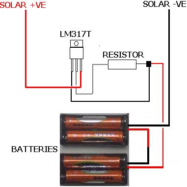
The following circuit illustrates the LM317T IC designed for a solar battery charger circuit diagram. Features include a simple circuit suitable for AA and AAA rechargeable batteries. The LM317T is a versatile linear voltage regulator that can be used in...
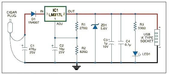
USB car charger adapter circuit design using LM317 regulator circuit The USB car charger adapter circuit utilizing the LM317 voltage regulator is designed to convert a car's 12V DC power supply into a stable 5V output, suitable for charging USB-powered...
The ASUS Eee is an ultra-portable notebook that meets the essential needs of tech enthusiasts while maintaining excellent build quality and affordability. In New Zealand, it can be purchased exclusively from DSE, where it is competitively priced compared to...
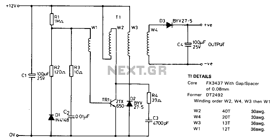
This circuit is designed to charge NiCad battery packs within the voltage range of 4.8 to 15.6 V using a convenient remote power source, such as an automobile battery. Upon initial power application, a small bias current supplied by...
Mobile phone chargers available in the market are quite expensive. The circuit presented here serves as a low-cost alternative to charge mobile telephones or battery packs with a rating of 7.2 volts. The proposed circuit design utilizes a straightforward approach to...
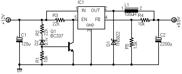
The following circuit illustrates a simple battery charger equipped with a temperature sensor. This circuit is based on the LM350 integrated circuit. Features include negative... The circuit utilizes the LM350 voltage regulator IC, which is known for its ability to...