
Wien Bridge Sine Wave Oscillator

Amplifier loop gain is a critical parameter in the design of audio and signal processing systems. It directly influences the fidelity of the output signal, particularly in applications requiring precise waveform reproduction, such as sine wave generation. The challenge arises from the need to balance gain with stability; excessive gain can lead to distortion, while insufficient gain may result in an inadequate output level.
To produce a low distortion constant amplitude sine wave, it is essential to implement feedback mechanisms within the amplifier circuit. Negative feedback can be employed to stabilize the gain and minimize distortion. This involves routing a portion of the output signal back to the input in a manner that counteracts any deviations from the desired output. The feedback loop can be designed using operational amplifiers, which provide high input impedance and low output impedance, making them ideal for this purpose.
Additionally, the selection of components plays a crucial role in the performance of the amplifier circuit. High-quality resistors and capacitors with low tolerance levels should be used to ensure precision in the feedback network. Moreover, the bandwidth of the amplifier must be considered to ensure that it can handle the frequency range of the sine wave without introducing phase shifts that could lead to further distortion.
The use of simulation tools can aid in optimizing the loop gain and feedback configuration. By modeling the amplifier circuit, engineers can analyze the frequency response and distortion characteristics, allowing for adjustments to be made before physical implementation. This iterative process can significantly enhance the overall performance of the sine wave generator.
In conclusion, while achieving the right amplifier loop gain is a complex task, employing negative feedback, selecting high-quality components, and utilizing simulation tools can effectively mitigate distortion and ensure the generation of a constant amplitude sine wave.Getting the right amplifier loop gain is the major problem in producing a low distortion constant amplitude sine wave. However, we can solve this problem with.. 🔗 External reference
Related Circuits

A series of LEDs that turn on and off in a precise sequence, creating a calming and hypnotic effect. Various LED chaser, scanner, and sequencer circuits exist, utilizing discrete transistors, logic integrated circuits (ICs), or microcontrollers. However, a common...
The frequency formula of a 555 oscillator is well-known. For given resistors and capacitors, the frequency can be calculated using a specific formula derived from mathematical principles. The 555 timer IC is widely used in various applications, including oscillators, timers,...
These circuits could be used as the basis for Model Railroad DCC Boosters or PWM motor controllers. The first schematic is for a basic 3 Amp - DCC Booster using the LMD 18200 CMOS, H-Bridge. Included in the design...
This circuit generates sine waves ranging from 1 kHz to 25 kHz with a total harmonic distortion (THD) of better than -80 dB. It comprises a 4th-order low-pass filter and a TTL counter. The circuit utilizes a sine wave oscillator...
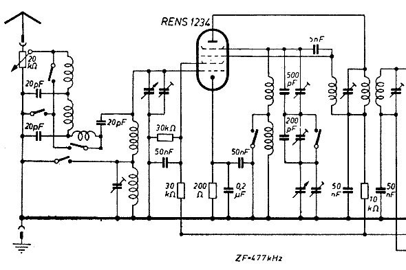
The schematic of the mixer section illustrates an oscillator. The oscillator's LC circuit has only two connections to the valve and does not include a tap or tickler coil. Oscillations will only occur if the tube provides a negative...
This is a kHz sine wave generator circuit built based on the configuration of an inverted Wien bridge (see C1-R3 C2-R4). R5 and R7 are used for output amplitude setting. Set R5 to read 1V RMS on an audio...