
Square Wave Oscillator with Minimum Components Count

The square wave generator circuit is designed to produce a periodic waveform that alternates between a high and a low state, making it suitable for various applications in electronics, including clock signals for digital circuits and AC drive signals for sensor excitation. The key components typically involved in this type of circuit include resistors, capacitors, and active devices such as operational amplifiers or transistors.
In a basic square wave generator, a resistor-capacitor (RC) network is often used to determine the frequency of oscillation. The charging and discharging of the capacitor through the resistor creates a time delay that defines the duration of the high and low states of the output waveform. The output can be taken from a comparator or a transistor that switches states based on the voltage across the capacitor.
For instance, in a simple astable multivibrator configuration using two NPN transistors, the circuit can be designed to toggle between the high and low states based on the feedback from the output to the base of the transistors. This arrangement allows for the generation of a continuous square wave without requiring any external triggering.
The frequency of the output square wave can be adjusted by changing the values of the resistors and capacitors in the circuit. Additionally, the duty cycle, which determines the proportion of time the signal is high versus low, can also be modified by manipulating these component values.
In practical applications, square wave signals can drive various loads, including relays, LEDs, and other electronic components. The waveform's characteristics, such as rise and fall times, can be influenced by the circuit design and component selection, ensuring compatibility with the intended application. Overall, the square wave generator circuit is a fundamental building block in electronic design, providing essential timing and control signals across a wide range of devices.This circuit generates a square-wave which is useful as a clock signal or AC drive for the excitation of sensors. this article presents a square-wave. 🔗 External reference
Related Circuits
The output frequency can be altered based on the division ratio of the comparison frequency in the 10 kHz unit, with the division ratio set to 1024 in this circuit. Given that the amateur radio bandwidth in Japan is...
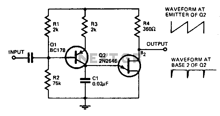
With the component values shown, the oscillator has a frequency of 8 kHz. When an input signal is applied to the base of Q1, the current flowing through Q1 is varied, thus affecting the time required to charge C1....
Generating variable audio frequencies with crystal precision is challenging due to the scarcity of low-frequency quartz crystals, which typically produce a single frequency. While minor adjustments to the frequency of a crystal oscillator can be made using a trimmer...
The SK1901 is a semiconductor integrated circuit that employs the Hall effect. It is specifically designed to function in alternating magnetic fields, particularly at low supply voltages and across a wide temperature range, up to +125°C. This Hall integrated...

This is a circuit known as a Wien bridge oscillator circuit. The circuit features both positive and negative feedback loops and operates under the control of an operational amplifier (op-amp). The oscillation frequency is determined by the RC time...
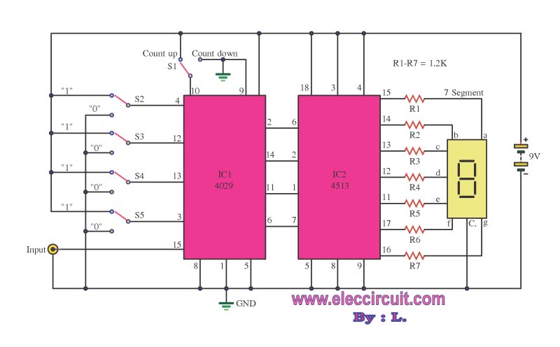
This is a simple digital counter circuit utilizing the IC 4029 to process binary data, which is then sent to the IC 4513, a driver IC for a 7-segment display to show the output. The digital counter circuit is designed...