
9V Speaker polarity Checker

To determine the correct polarity, the left (L) and right (R) outputs of the circuit are connected to an amplifier. Adjusting the frequency via P1 alters the sound characteristics. If the speakers are properly polarized at low frequencies, the sound localization will be clear. Conversely, at high frequencies, the sound will appear centralized. When the speakers are incorrectly polarized, the opposite effect occurs. P1A and P1B are configured as a single stereo potentiometer. The power supply for the circuit can be a 9V battery.
R1 = 470 kOhm
R2 = 68 kOhm
R3 = 6.8 kOhm
R4, R11, R14 = 4.7 kOhm
R5 = 56 kOhm
R6 = 47 kOhm
R7, R8 = 2.7 kOhm
R9, R12 = 2.2 kOhm
R10, R13 = 100 Ohm
P1 = 4.7 kOhm stereo
C1 = 330 nF
C2, C3, C4 = 27 nF
C5, C6 = 100 nF
C7-C10 = 10 µF
T1-T4 = BC 547B
The circuit is designed to enhance the listening experience by ensuring proper speaker polarity, which is crucial for stereo sound quality. The use of transistors allows for effective signal processing, while the adjustable filter enables fine-tuning of the audio output. The inclusion of various resistors and capacitors aids in stabilizing the circuit and shaping the frequency response, ensuring optimal performance across the audio spectrum. The choice of a 9V battery as a power supply provides a convenient and portable solution for powering the circuit, making it suitable for various applications in audio systems.In a stereo system is often whether the speakers are polarized. This is especially a problem if the cable has no polarity. This circuit will help with the proper terminals of the speakers. The circuit consists of four transistors. T1 generates a noise signal. T2 is built around a filter with adjustable P1A. Through this signal T5 is on the right channel. Phase shifter with a T3 is built. Through this signal T4 is applied to the left channel. Determining the correct polarity is as follows: The L and R outputs of the circuit to the amplifier. By turning the frequency of P1 is changed. If the speakers are polarized at low frequencies then the location of the sound is uncertain. At high frequencies, the sound comes off the middle. When improperly pooled loudspeakers, the opposite effect. P1A and P1b are one stereopotmeter. The power supply can be a 9 V bokbatterij. Parts List R1 = 470 kOhm R2 = 68 kOhm R3 = 6.8 kOhm R4, R11, R14 = 4.7 kOhm R5 = 56 kOhm R6 = 47 kOhm R7, R8 = 2.7 kOhm R9, R12 = 2.2 kOhm R10, R13 = 100 ? P1 = 4.7 kOhm stereo C1 = 330 nF C2, C3, C4 = 27 nF C5, C6 = 100 nF C7-C10 = 10 uF T1-T4 = BC 547B
🔗 External reference
Related Circuits
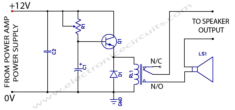
When powering on a power amplifier, a loud thump sound occurs due to a sudden heavy discharge current through the speaker. This current has the potential to damage the speaker, particularly in the case of a direct-coupled amplifier. The phenomenon...
This is a CMOS IC (CD4033) based circuit which can be used to detect presence of mains AC voltage without any electrical contact with the conductor carrying AC current/voltage. Thus it can be used to detect mains AC voltage...
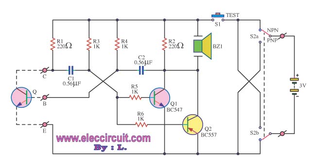
The transistor was checked by measuring the resistance between its various pins. Occasionally, issues arise when measuring the resistance between them. The process of measuring resistance in a transistor is an essential diagnostic technique used to evaluate its functionality. A...
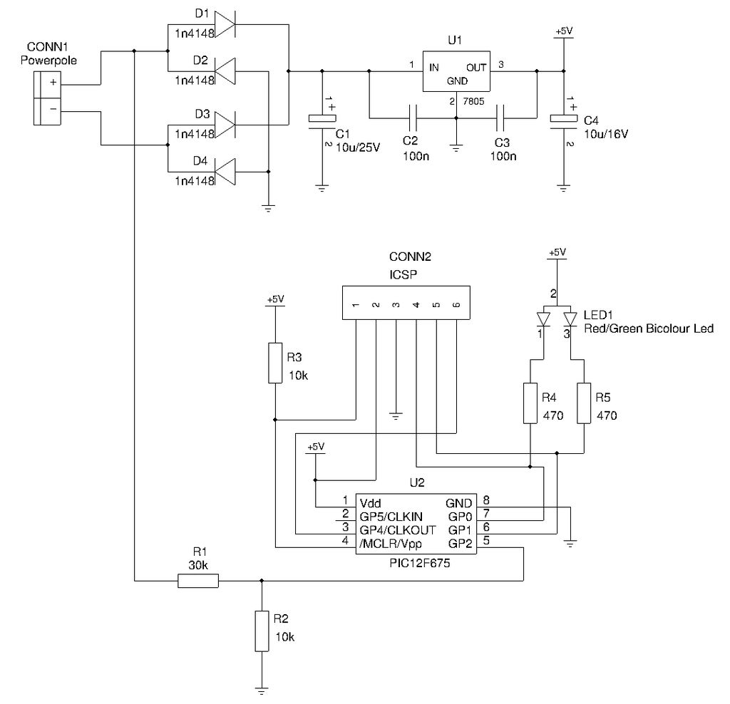
This is a compact device designed for amateur radio (HAM) enthusiasts, utilizing Powerpole connectors to interface HAM equipment with an unidentified power supply that also features Powerpole connectors. The device functions as an essential accessory for HAM radio operators,...
This original design is a variation on a well-known design, examples of which can be found in a great many texts. My variation was to add a second differential stage to replace the usual common emitter-plus-constant current source. Doing...
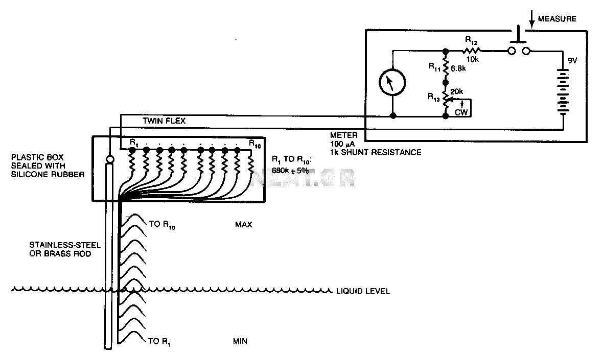
Although many circuits utilize the varying-capacitance method for measuring liquid levels, this straightforward resistive circuit is significantly easier to construct. Even a tank containing a liquid, such as water, has sufficient conductive salts in solution for this method to...