
Mains Voltage Checker

The described circuit utilizes a CD4033 CMOS integrated circuit, which functions as a decade counter, to detect the presence of alternating current (AC) voltage without direct electrical contact with the conductor. The operation is based on the principle of capacitive coupling, where the sensing probe, positioned near the conductor, detects the electric field generated by the AC voltage.
When the sensing probe is brought into proximity with an AC-carrying conductor, an electric field is induced in the probe. The high input impedance of the CMOS IC ensures that even a small induced voltage can effectively trigger the clock input of the CD4033. This results in the counter advancing through its count sequence from 0 to 9, with the display updating rapidly to reflect this count. The rapid cycling of the displayed digits serves as an indication of the presence of mains AC voltage. In the absence of AC voltage, the display will show a random digit from 0 to 9, indicating that the circuit is not detecting any voltage.
For power supply, a compact 9-volt PP3 battery is recommended, providing sufficient voltage and current for the CMOS IC and ensuring portability of the device. The design emphasizes safety and ease of use, allowing users to detect AC voltage without the need for invasive contact with the electrical conductor, thus maintaining insulation integrity and reducing the risk of electric shock. The simplicity of the circuit design, combined with the effectiveness of the CD4033 in counting and displaying, makes this a practical solution for voltage detection in various applications.This is a CMOS IC (CD4033) based circuit which can be used to detect presence of mains AC voltage without any electrical contact with the conductor carrying AC current/voltage. Thus it can be used to detect mains AC voltage without removing the insulation from the conductor. Just take it in the vicinity of the conductor and it would detect presence of AC voltage. If AC voltage is not present, the display would randomly show any digit (0 through 9) permanently. If mains supply is available in the conductor, the electric field would be induced into the sensing probe. Since IC used is CMOS type, its input impedance is extremely high and thus the induced voltage is sufficient to clock the counter IC.
Thus display count advances rapidly from 0 to 9 and then repeats itself. This is the indication for presence of mains supply. Display stops advancing when the unit is taken away from the mains carrying conductor. For compactness, a 9-volt PP3 battery may be used for supply to the gadget. 🔗 External reference
Related Circuits

The circuit is illustrated. A standard driving transistor requires a higher breakdown voltage transistor (such as the FIG driving tube 9013). As the output voltage rises, the bias on VT55 increases, leading to an increase in the forward current...
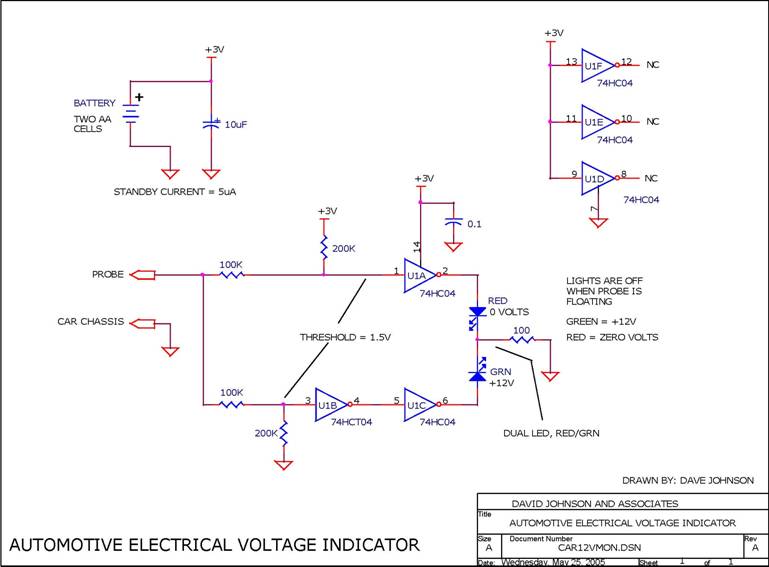
When troubleshooting the 12V electrical system of an automobile, it is beneficial to have a simple voltage indicator tool instead of a voltmeter. This electronic circuit is powered by two AA batteries or two N cells, providing sufficient energy...
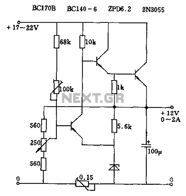
The circuit output voltage can be continuously adjusted from zero to its maximum value. The baseline is established by a constant current sourced from the auxiliary power supply circuit. The reference current of 500 microamperes can be fine-tuned to...
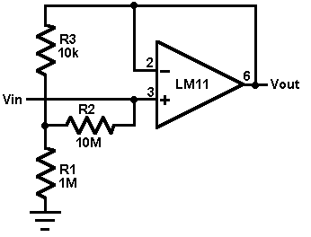
This circuit utilizes an LM11 operational amplifier configured as a voltage follower with an input resistance of 1 GΩ, constructed using standard resistor values. When the input is left disconnected, the input offset voltage is amplified by the same...

This circuit diagram indicates when the input voltage deviates from two defined limits, V1 and V2. The limits are adjustable, and the circuit is designed to trigger the adjustable window. The supply voltage, Vcc, must be at least 2...

The inverting input is maintained at a low level via a 10K resistor when the circuit is powered on but not in use. During measurement activities, including calibration measurements where the input is floating, this resistor is disconnected. The...