
A 40 meter QRP - Transceiver

The transceiver circuit described is a fundamental design that combines both transmitter and receiver functionalities, typically utilized in amateur radio applications. The circuit operates within a specified frequency range, often adjustable via a variable capacitor or inductor to accommodate different communication bands.
Key components of the design include a radio frequency (RF) amplifier, which enhances the signal strength for both transmission and reception. The RF amplifier typically utilizes bipolar junction transistors (BJTs) or field-effect transistors (FETs) for their high gain characteristics. A mixer stage is employed to combine the incoming RF signal with a local oscillator signal, enabling frequency conversion to an intermediate frequency (IF) for further processing.
The transmitter section incorporates a modulator circuit, which can be either amplitude modulation (AM) or frequency modulation (FM), depending on the intended application. This modulator is essential for encoding the audio signal onto the RF carrier wave. A low-pass filter is often used post-modulation to suppress unwanted harmonics and ensure a clean output signal.
In the receiver section, a bandpass filter is crucial to select the desired frequency while rejecting adjacent channel signals. After the mixer stage, the IF signal is amplified and demodulated to retrieve the original audio signal. The audio output can be connected to a speaker or headphones for listening.
Power supply considerations are also vital; the circuit typically operates on a regulated DC voltage, often sourced from batteries or a power adapter. Proper decoupling capacitors are included to minimize noise and ensure stable operation.
This transceiver design serves as a foundational project for beginners, providing insights into RF principles, circuit design, and practical implementation of communication systems. While advancements in technology may suggest improved designs, the principles demonstrated in this circuit remain relevant for educational purposes and experimentation in the field of electronics.This was one of my very first transceiver developments. This page was also one of the very first circuit descriptions that I put on the internet quite some years agon. Today I would not build a transceiver like I did then, but it was working, so I have kept this page for historical (and sentimental) reasons.
If you are a beginner in building you own transceivers you might be able to steal a few of my ideas. Please let me know if you do a full copy of the design, I would be interested in you practical experiences when operation on the air. 🔗 External reference
Related Circuits
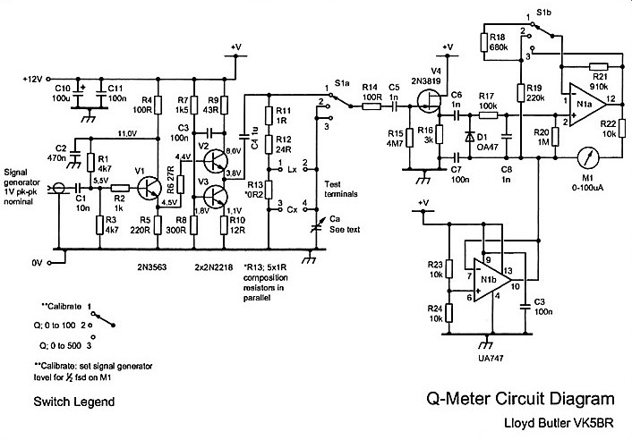
The Q meter has been an essential piece of equipment for laboratories engaged in the testing of radio frequency circuits. In modern laboratories, the Q meter has been largely replaced by more advanced and costly impedance measuring devices, making...
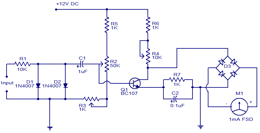
This is a simple circuit that functions as a tachometer. It operates as a frequency-to-current converter, transforming the incoming signal into a proportional current to drive the meter. The deflection on the ammeter correlates directly with the frequency of...
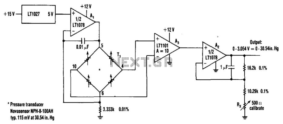
Using the Linear Technology LT1027 reference and LT1078 operational amplifiers, transducer T1 is supplied with 1.5 mA. The pressure transducer requires an amplifier with a gain of 10, followed by a voltage follower. The output can drive either an...
Interface the LCD with the 8051 microcontroller AT89S52. However, upon powering up the microcontroller, the LCD displays only black boxes. Multiple codes have been tried, but the output remains the same. The circuit has been simulated in Proteus, where...
When an antenna is attached, or even if not, in the presence of a strong RF field, the field strength meter has a moving coil meter to indicate relative field strength. The box holds a Schottky diode detector, a...
This pyrometer is used to measure the temperature of an incandescent body. The principle behind this measurement is that the hotter the body, the spectrum of the emitted radiation will shift. A pyrometer is a non-contact temperature measurement device that...