
Low-Cost Barometer

The circuit utilizes the LT1027 precision voltage reference to provide a stable reference voltage for the LT1078 operational amplifier. The LT1078 is configured to amplify the output signal from the pressure transducer, T1, which operates at a current of 1.5 mA. The transducer generates a small voltage signal that corresponds to the pressure it measures. To ensure that this signal is suitable for further processing, it is necessary to amplify it.
The gain of the amplifier is set to 10, which means that the output voltage will be ten times the input voltage from the transducer. This is achieved by configuring the feedback and input resistors of the LT1078 in accordance with the standard non-inverting amplifier configuration. Following the amplification stage, a voltage follower (also known as a buffer) is implemented to isolate the amplifier from the load. The voltage follower is configured using another LT1078 op-amp, ensuring that the output voltage remains unchanged while providing high input impedance and low output impedance.
The final output from the voltage follower can be directed to either an analog meter or a digital voltmeter (DVM) circuit. The choice of output device depends on the application requirements. An analog meter provides a visual representation of the pressure reading through a moving needle, while a DVM offers a digital display that can provide more precise readings. The circuit design ensures that both output options can be utilized without the need for additional components, making it versatile for various measurement applications. Using Linear Technology LT1027 reference and LT1078 op amps, transducer T1 is fed with 1.5 mA. The pressure transducer f eeds an amplifier with a gain of 10, then it feeds a voltage follower. Output can either drive an analog meter or a DVM circuit.
Related Circuits

Author Jim Walker describes a very low-cost analog delay line circuit using components such as the LM311 comparator and 74HC74 D flip-flop. The analog delay line circuit presented by Jim Walker utilizes the LM311 comparator and the 74HC74 D flip-flop...
This low-cost function generator, based on the Maxim MAX038 high-frequency waveform generator, produces sine, triangle, and square waves from under 1 Hz to over 20 MHz. The function generator utilizing the Maxim MAX038 is designed to provide a versatile range...
Applying the filtered and rectified AC input to a high-input-voltage linear regulator is the simplest way to produce a low current level from an AC source. The process of converting an AC source to a low current level using a...
This application note provides a concise overview of power amplifier theory and presents simulation results that offer insights into the operation of the power amplifier across all of MAXIM's LFRF transmitters and transceivers. Power amplifiers are critical components in communication...
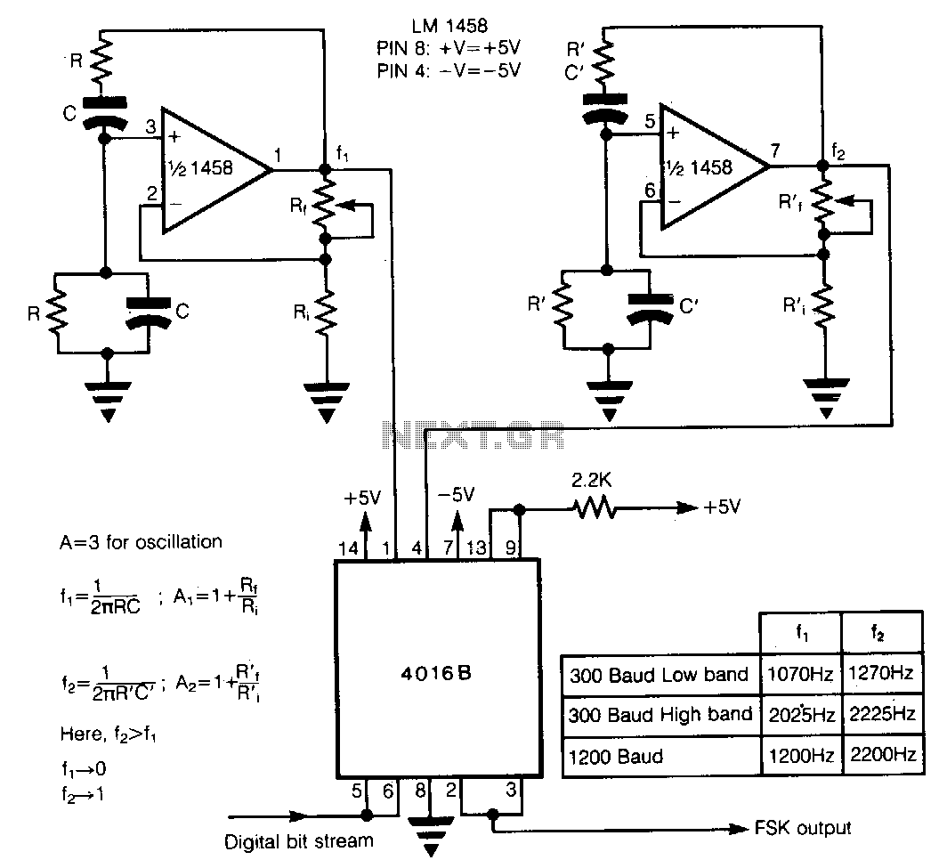
In Frequency Shift Keying (FSK), two distinct frequencies are utilized to represent the binary digits 0 and 1. The core of the circuit comprises two Wien-bridge oscillators constructed with a dual operational amplifier LM1458, each generating one of the...
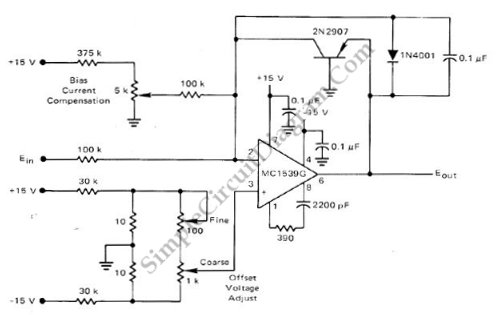
This low-cost logarithmic converter is constructed using an operational amplifier (op-amp) and a transistor. The circuit utilizes a Motorola MC1539G op-amp connected to a PNP transistor. The logarithmic converter circuit is designed to convert linear input signals into logarithmic output...