
A block diagram of AN6657 and basic application circuit

The AN6657 and AN6657S integrated circuits are designed for motor control applications, specifically for driving DC motors with bidirectional capability. The internal H-bridge configuration allows for efficient control of motor direction and speed by utilizing pulse width modulation (PWM) techniques. The device is capable of handling the required current levels to operate small to medium-sized motors, making it suitable for various applications, including robotics, automation systems, and consumer electronics.
In operation, the H-bridge driver outputs on pins 5 and 8 are responsible for controlling the polarity of the voltage applied to the motor terminals. When pin 5 is activated (set to a high logic level), current flows through the motor in one direction, causing it to rotate forward. Conversely, activating pin 8 reverses the polarity, allowing the motor to rotate in the opposite direction. The ability to control motor speed is achieved by modulating the duty cycle of the PWM signal applied to the enable pin, which is typically connected to an external control circuit.
The positive supply voltage for the H-bridge is provided through pins 9 and 11. This supply voltage must be stable and within the specified operating range to ensure reliable motor operation. Additionally, the external electrical contact resistance (R VCC) plays a crucial role in limiting the current and protecting the integrated circuit from overcurrent conditions.
Pin 6 serves as the connection point for the H-bridge arm, while the external NPN transistor connected to this pin is utilized to ground the circuit, enabling or disabling the motor operation based on the control signals. This configuration allows for enhanced control over the motor's behavior, including features such as braking and coasting.
Overall, the AN6657 series provides a compact and efficient solution for motor control applications, integrating essential features into a single package to simplify design and implementation.AN6657 is a 16-pin dual in-line plastic package, AN6657S 16-pin dual flat plastic package. 1. Speed Control works with internal H-bridge driver chip circuit, 5 and 8 feet H-bridge driver output, then charged motor. When 5 feet is positive, the motor is transferred; when 8 feet is positive, reverse the motor. H-bridge positive supply 9 and 11 feet, after an external electrical contact resistance r vcc. H bridge arm connected to 6 feet, after an external NPN transistor is grounded, see solid
Related Circuits
In applications where a MOSFET is employed to switch a load, incorporating short-circuit or overload protection is straightforward. This can be achieved by utilizing the internal resistance RDS(ON) of the MOSFET, which generates a voltage drop proportional to the...
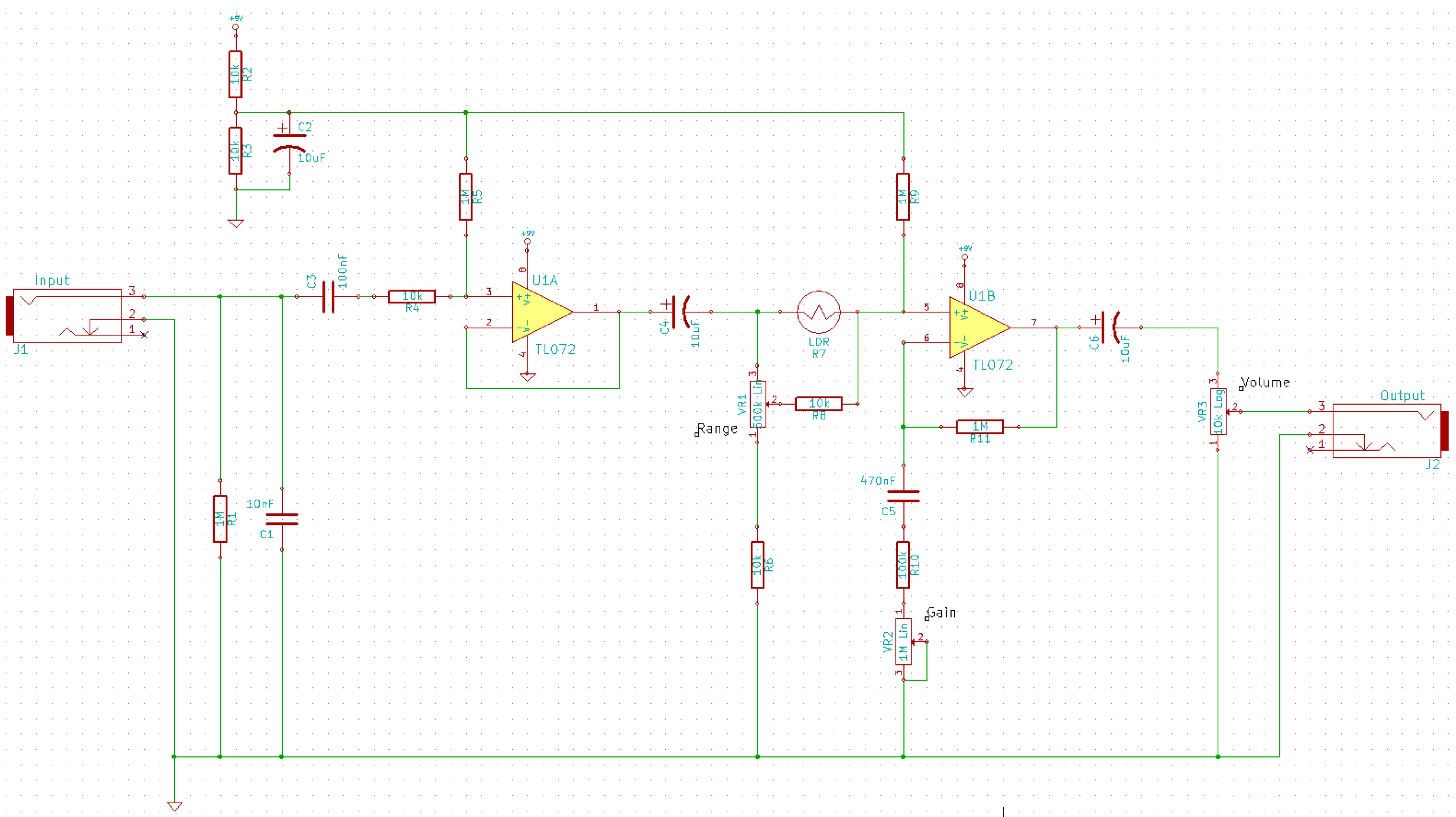
This is a simplified schematic for the Solar Lifeforce. The design eliminates the expression/CV output features and the toggle for the buffer, making it a straightforward circuit. It may benefit from adding small capacitors between R5 and ground, as...
This is a car alarm simulator that uses an LED as a simulation output. This simple circuit can indicate whether a car is running or not by detecting the voltage difference when the car is on or off. This...
The LM1036 is a DC controlled tone (bass/treble), volume and balance circuit for stereo applications in car radio, TV and audio systems. An additional control input allows loudness compensation to be simply effected. Four control inputs provide control of...
Light flashing circuit. This circuit is designed to create a small lamp that flashes with a signal at a rate of one flash per second, controlled by adjusting the lamp voltage through resistor R1. The rate is adjustable to...
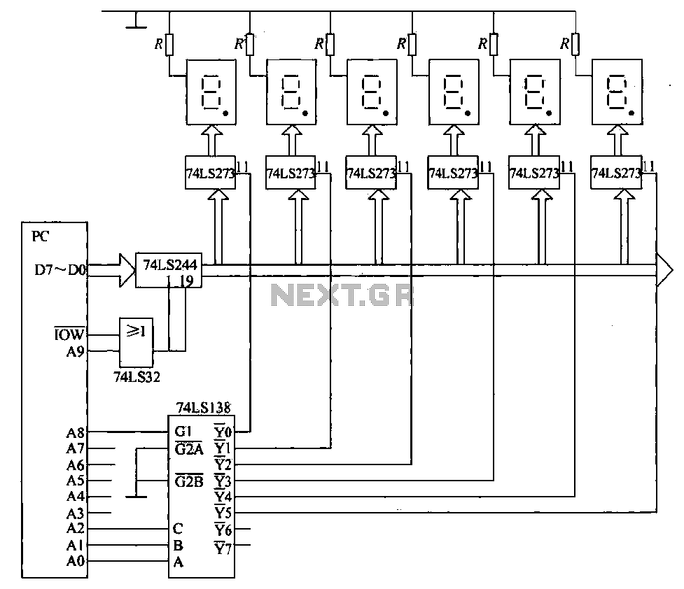
The static display circuit is illustrated in Figure 6. The 74LS244 acts as bus drivers, and six figures represent a public bus, each equipped with an LED display latch (like the 74LS273) connected to the code for latching the...