
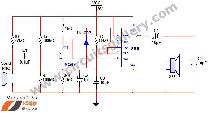
A circuit diagram of a wireless hands-free telephone device

The wireless hands-free telephone device circuit diagram typically comprises several key components that work together to enable hands-free communication. The primary components include a microphone, speaker, Bluetooth module, power supply, and control circuitry.
The microphone captures the user's voice and converts it into an electrical signal. This signal is then processed by the control circuitry, which may include an operational amplifier for signal conditioning. The processed audio signal is transmitted wirelessly via the Bluetooth module, which allows for connectivity with a compatible mobile phone or other communication devices.
On the receiving end, the Bluetooth module decodes the incoming audio signal and sends it to the speaker, which converts the electrical signal back into sound waves, allowing the user to hear the other party. The power supply, often a rechargeable battery, provides the necessary voltage and current to power the entire circuit, ensuring that all components operate effectively.
Additional features may include volume control, LED indicators for connection status, and noise cancellation circuitry to enhance audio clarity. The layout of the circuit should be designed to minimize interference and optimize performance, ensuring reliable hands-free communication in various environments. Overall, the wireless hands-free telephone device circuit diagram illustrates a sophisticated integration of components that facilitate convenient and efficient communication.A wireless hands-free telephone device circuit diagram as follows:
Related Circuits

The schematic for this project flows naturally from left to right, starting with the antenna and the regenerative receiver front-end, followed by amplification stages, and concluding with the 555 timer. This regenerative receiver front-end is commonly found in circuits...
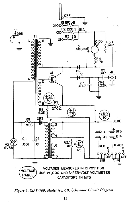
This is the schematic for the 6A model located at the bottom of the unit, which is incorrect. These units have been subjected to movement for over 40 years, leading to many bottoms being swapped due to battery corrosion...
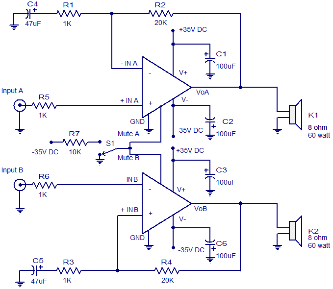
The circuit diagram presented is for a 2 x 60 Watt stereo amplifier utilizing the LM4780 from National Semiconductors. The LM4780 is an excellent audio amplifier integrated circuit capable of delivering 60W RMS power output per channel into 8-ohm...
A battery-status indicator circuit is useful for monitoring portable test equipment and similar devices. LED D1 flashes to attract the user's attention, signaling that the circuit is operational, preventing it from being left on unintentionally. The circuit produces approximately...
This house FM transmitter for your stereo or any other amplifier provides good signal strength up to a distance of 500 meters with a power output of approximately 200 mW. It operates on a 9V battery. The audio-frequency modulation...
This document discusses a simple project utilizing the 555 timer IC. The 555 timer IC can be configured as an audio amplifier using an astable multivibrator configuration. It performs pulse width modulation (PWM) on an audio signal. The current...