
A Cmos Based Single Zone Alarm circuit

The circuit operates through a combination of resistors, capacitors, and transistors to manage the timing and functionality of the alarm system. The exit and entry delays are crucial for providing users with adequate time to leave and re-enter the building without triggering the alarm unintentionally. The use of a timed bell cut-off adds an additional layer of control, allowing users to silence the alarm after a period. The integration of both normally-open and normally-closed switches enhances flexibility, permitting various configurations based on user preference and specific application requirements.
The design should ensure that all components are rated appropriately for the voltages and currents they will encounter, particularly the resistors and the buzzer, which must handle the specified sound output without distortion. The inclusion of a transistor, such as Q3, for the reset function is critical for maintaining the integrity of the alarm system; it allows for a controlled reset process that minimizes false alarms while ensuring that the system remains vigilant.
The circuit layout should be organized to minimize interference and noise, especially in the areas where sensitive components like the inertia sensors are connected. Proper grounding and shielding techniques should be employed to protect against false triggering due to environmental factors. Overall, this alarm system design is robust and adaptable, making it suitable for a wide range of security applications.This circuit features automatic Exit and Entry delays - timed bell cut-off - and system reset. It has provision for normally-open and normally-closed switches - and will suit all of the usual input devices (Pressure Mats, Magnetic Reed contacts, Foil Tape, PIRs and Inertia-Sensors). If the green LED is not lighting - check for an open window or do or etc. Once you`re satisfied that the building is secure - and the green LED is lighting - move SW1 to the "set" position. At this point - the red LED will light - and the Exit Delay will begin. The length of the Exit Delay is set by the value of R12. With a 220k resistor - you have about 30 to 40 seconds to leave the building. As you do so - the Buzzer will sound. It should stop sounding when you close the door behind you. This indicates that the trigger circuit has been successfully restored within the time allowed. When you return to the building and open the door - the Buzzer will sound - and the Entry Delay will begin.
The length of the Entry Delay is set by the value of R8. With a 470k resistor- you`ll have about 30 to 40 seconds to move SW1 to the "off" position. If you fail to do so - the Siren will sound. The length of time the Siren sounds is set by R11. With a 4M7 resistor it will sound for about 15 to 20 minutes. Then the relay will drop out - and the alarm will attempt to reset itself. It does this by using Q3 to switch itself "off" briefly. If the trigger circuit has been restored - the alarm will reset. If not - the attempt will fail - and the alarm will reactivate. It will go on trying to reset itself every 15 to 20 minutes - until either the trigger circuit is restored - or the alarm is switched off. All the usual triggering devices may be connected to the input terminals. These include Inertia-Sensors. The sensitivity of the Sensors is adjusted by R4. Set to minimum value - a light tap will activate the alarm. Set to maximum value - a heavy blow is required. If you are not using Inertia Sensors - replace R4 with a 220k fixed resistor. If you are not using normally-open switches - you can leave out R1, C1 & Q1 - but you must fit an extra link between the Green Led and C2.
🔗 External reference
Related Circuits
L1 is 0.112uH (this tunes to the middle of the FM band, 98 MHz, with VC1 at its centre value of 33pF). L1 is 5 turns of 22 swg enamelled copper wire close-wound on a 5mm (3/16") diameter former....
Most universal radio receivers have a very wide bandwidth that is not particularly suitable for radio amateurs. The better models with narrower bandwidth are almost a... Universal radio receivers are designed to operate over a broad frequency range, making them...
The UC3842, UC3843, UC3844, and UC3845 series of oscillators can generate synchronization pulses without requiring numerous external components. The following circuit illustrates the Sync Pulse Generator Circuit Diagram for the UC3842/3/4/5. This sync pulse circuitry is capable of operating...
The quartz crystal oscillator circuit is highly advantageous in terms of frequency stability. Even the Voltage-Controlled Crystal Oscillator (VCXO) circuit, which allows for significant frequency changes, typically experiences only about a 1% variation. However, the linear range of control...
D1, D2, C1, and C2 double the AC input voltage, charging capacitor C3 through resistor R1 to approximately 320 volts. Resistor R1 isolates the voltage doubler from the discharge capacitor C3, ensuring that capacitors C1 and C2 do not...
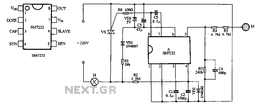
The core component of the circuit is the dimmer, utilizing the SM7232 integrated circuit. The pin configuration includes: 1) VDD, the positive power supply terminal; 2) DOZE; 3) CAP; 4) SYN, which synchronizes input power frequency using an internal...