
A CMOS the spot welding time adjustment circuit b

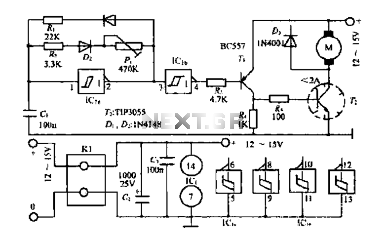
The described circuit employs complementary metal-oxide-semiconductor (CMOS) technology to facilitate precise control over the timing of spot welding operations. The cycle adjustment feature is crucial for optimizing the welding process, allowing users to select the appropriate duration for different materials and thicknesses. The range of 1 to 99 cycles provides flexibility, although typical usage often requires fewer cycles, with a common setting around 10.
The integration of gates (C036) serves as the logic control elements, enabling the configuration of the desired cycle count. The counters (C180) play a vital role in tracking the number of cycles completed during the welding process, ensuring accurate timing and repeatability. The D flip-flops (C043) are utilized to store the state of the control signals, providing a stable output that can be used to trigger the welding operation.
Additionally, the inclusion of a seven-segment decoder (C036) enhances user interaction by displaying the selected cycle count on an LED display (BS202). This feature allows operators to easily monitor and adjust settings in real-time, contributing to improved operational efficiency and safety.
Overall, the CMOS-based spot welding time adjustment circuit is a sophisticated solution that combines various electronic components to deliver precise control and user-friendly operation, making it suitable for a range of industrial applications.A CMOS constituting the spot welding time adjustment circuit b The number of cycles it uses CMOS device composed of a control circuit, optionally in the range of 1 to 99 cycles to choose from. In actual use, most of them within 10 cycles adjusted enough. Drawing, are integrated with CMOS circuitry; gates 1 to 20 available C036; C180 counter available 21,22; D flip-flops 25, 26 Available C043; seven segment decoder applications C036; LED digital works BS202.
Related Circuits
Presented circuit is very simple. With more sampling, I refrained from using the converter and lamp designed for powering three NiCd or NiMH batteries. Because the voltage difference between the battery and the LED is very small, this arrangement...
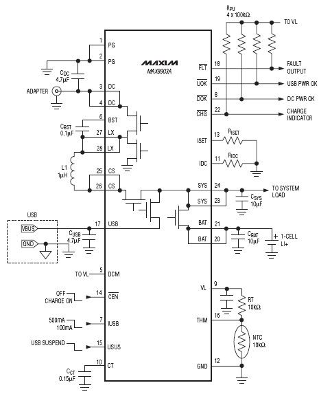
The DC input for this charger IC operates from 4.15V to 16V with a maximum protection limit of 20V. In contrast, the USB input has a voltage range of 4.1V to 6.3V, with protection up to 8V. The charger integrated...
Schematic and description of a simple and easy-to-build NiCd and NiMH battery charger circuit that is capable of charging multiple NiCd and NiMH batteries. The circuit for the NiCd and NiMH battery charger is designed to be straightforward, allowing for...
The core multi-resonant circuit 40 L06 has a collapse time of 1C. An auxiliary electric signal operates below its low threshold, opening Icl. The output is provided through two terminals for business use. The circuit includes components such as...
The main circuit of the 6-channel mixer consists of six input channels. Channels 1-4 are mono, while channels 5-6 are designed for music use. The number of input channels can be increased as desired. The output of each channel...
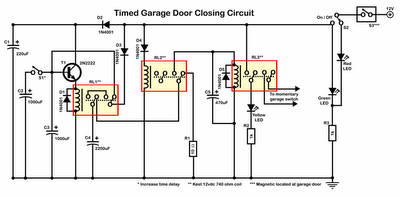
Timer garage door circuit schematic diagram, printed circuit board. The timer garage door circuit is designed to automate the opening and closing of a garage door based on a predetermined time interval. The schematic diagram illustrates the layout and connections...