
A control two water supply frequency control circuit a

The described circuit operates as a frequency control mechanism for two motors that regulate the pressure of water in a supply system. The primary function of this circuit is to maintain a constant pressure by adjusting the motor speeds based on feedback received from various sensors.
The fault output terminals (1 and 2) are crucial for monitoring the operational status of the motors. If an anomaly is detected, these terminals will relay fault signals to a monitoring system, allowing for timely maintenance or intervention.
The analog feedback current input terminals (6 and 7) receive signals from current sensors that monitor the actual motor performance. This feedback is essential for the control system to make real-time adjustments to the motor speeds, ensuring that the desired pressure levels are consistently achieved.
Analog output terminals (6 and 8) are used to provide data to other components of the system, such as a controller or display unit. This data can include information on current motor speeds or pressure levels, allowing operators to have a clear view of the system's performance.
The forward run terminals (19 and 20) are responsible for initiating the operation of the motors in a forward direction. These terminals are typically connected to a control switch or relay that activates the motors when water supply is required.
Programmable digital output terminals (11 and 20) allow for customization of the control circuit’s functions. These outputs can be programmed to perform specific tasks, such as activating alarms or controlling additional components based on the operational status of the motors.
Overall, this control circuit is integral to maintaining efficient operation in a constant pressure water supply system, ensuring that the motors function optimally while providing critical feedback and control capabilities.A control two (namely a frequency control two motors) Frequency constant pressure water supply control circuit shown in Figure 5-23. Figure, 1,2 fault output terminal; 6,7 anal og feedback current input terminals; 6,8 is the analog output of the sub; 19, 20 to run forward terminal; 11, 20 programmable digital output terminal.
Related Circuits
This generally results in a square wave if the frequency of oscillation is low enough relative to the amplifier's bandwidth. The schematic of a crystal-controlled oscillator features a low-frequency sine wave oscillator characterized by low distortion, wideband operation, and...
A selection of small self-contained CMOS alarm circuits is presented. The main features of each alarm are indicated on the circuit diagram itself. All circuits exhibit a very low standby current, making them suitable for battery operation. Each pair...
The circuit operates based on a principle where the SCR (Silicon Controlled Rectifier) trigger is grounded, keeping it in the off state. When a burglar triggers the alarm, a voltage is supplied to the SCR trigger, turning it on....
The delay time ranges from 0.5 to 3.5 seconds, which can be adjusted using the potentiometer RP to modify the delay duration. The circuit utilizes a timing mechanism that allows for the adjustment of delay intervals between 0.5 seconds and...
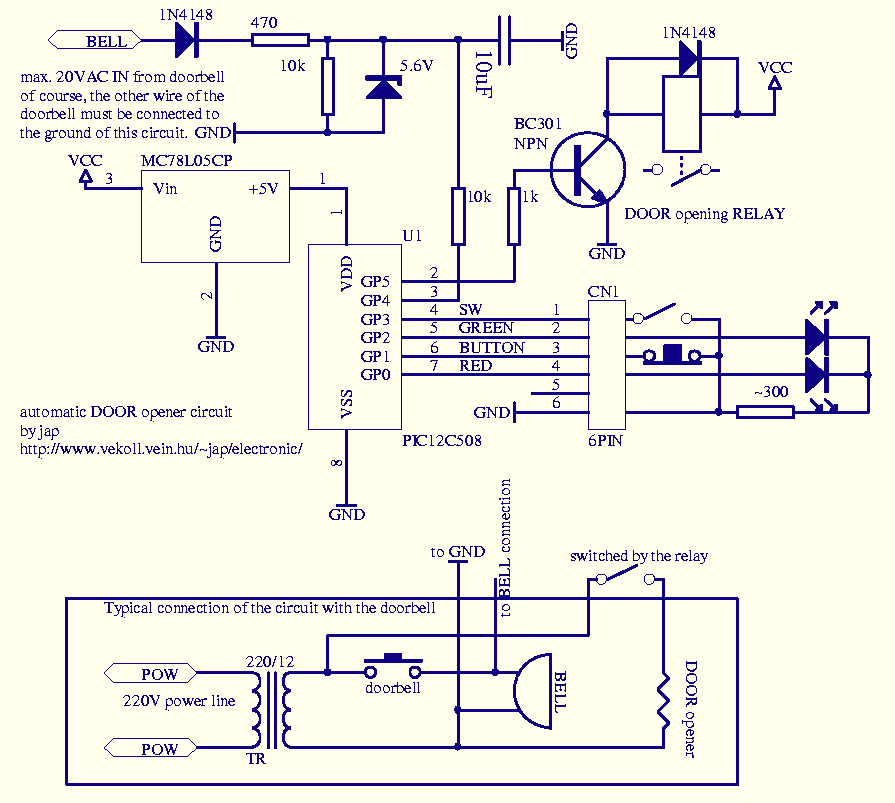
This circuit can be used to operate an electric strike or an electromagnetic lock on a door. It is not the door being opened/closed, but a small electromagnetic strike which unlocks the door. The opener has the following features...
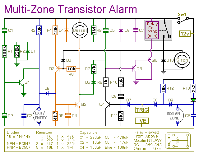
This transistor-based alarm features automatic exit and entry delays, along with a timed bell cut-off and system reset. In addition to the exit/entry zone, the basic alarm board includes one instant zone, which is sufficient for many applications. However,...