
Door lock Circuit

The described circuit is designed for controlling an electric strike or electromagnetic lock, providing enhanced security and convenience for door access. The primary function of the circuit is to activate the locking mechanism, allowing for the door to be unlocked upon receiving specific input signals.
The circuit includes three main operating modes:
1. **Automatic Operation**: This mode is triggered when a guest presses the doorbell. The circuit is designed to respond immediately by energizing the electromagnetic strike, thereby unlocking the door. The automatic feature can be enabled or disabled using a switch (SW), allowing for flexibility in operation based on user preference or security needs.
2. **Manual Remote Operation**: In this mode, the unlocking mechanism can be activated by pressing a designated button (BUTTON). This allows users to unlock the door remotely, providing convenience for users who may not be directly at the door. The BUTTON is connected to the control circuitry, which processes the input signal and activates the strike.
3. **Timer Delayed Operation**: This feature allows for a timed delay before the strike is activated. The delay can be programmed to suit various operational requirements, such as allowing time for the user to approach the door after the button is pressed or the doorbell is activated. The timing function can be implemented using a timer IC, which controls the duration that the strike remains energized.
The circuit may include additional components such as diodes for flyback protection, resistors to limit current, and capacitors for noise filtering. The power supply for the circuit should be selected based on the specifications of the electric strike or lock being used, ensuring that it can deliver sufficient voltage and current for reliable operation.
Overall, this circuit design provides a versatile solution for controlling door access through an electric strike or electromagnetic lock, incorporating both automated and manual operation modes for user convenience and enhanced security.This circuit can be used to operate an electric strike or an electromagnetic lock on a door. It is not the door being opened/closed, but a small electromagnetic strike which unlocks the door. The opener has the following features currently programmed in software: * automatic operation when a guest pushes the doorbell, the strike is operated immediately - can be set by a switch (SW) * manual remote operation - by pushing a button (BUTTON), the strike is operated immediately * timer delayed operation by p 🔗 External reference
Related Circuits
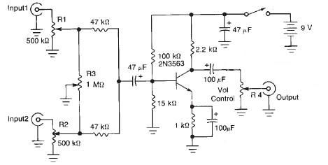
This audio mixer circuit diagram electronic project is designed using a few common electronic components. The audio mixer circuit project has two input channels. The input signal can be independently controlled using the R1 and R2 variable resistors. The...
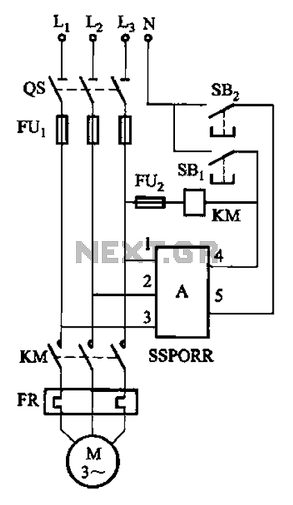
The solid-state phase failure relays for three-phase AC phase failure monitoring, protection, and control of new devices are referred to as SSPORR. This module consists of a five-terminal semiconductor configuration. Terminals 1, 2, and 3 serve as the three-phase...
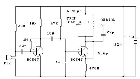
This FM transmitter circuit is very simple and has an acceptable transmission range. The signal transmitted from this FM transmitter circuit can be received at almost 300 meters in open air. The circuit requires a 3-volt operating voltage and...
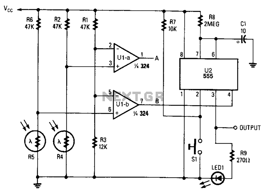
A combined monostable multivibrator using the 555 timer integrated circuit, along with a pair of light control comparators. This circuit can be utilized to control a load based on the timing parameters set within the circuit. The circuit comprises a...
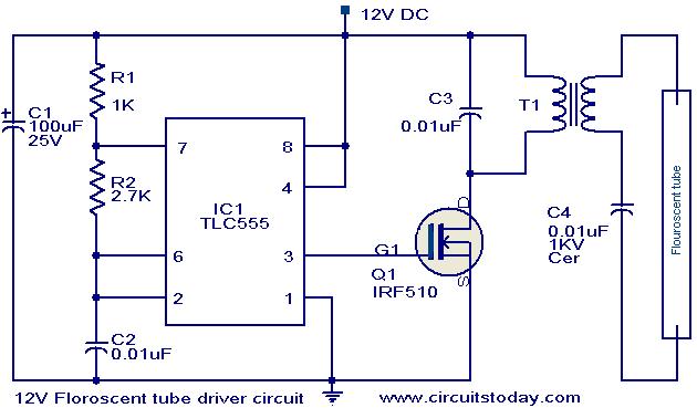
This circuit provides a simple and effective method for driving fluorescent lamps using a 12 V power supply. The circuit consists of an oscillator, a MOSFET switch, and a step-up transformer to power the fluorescent lamp. The TLC 555...
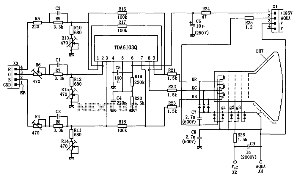
The circuit depicted in the figure integrates the TDA6103Q with a color picture tube, illustrating its practical application. The red, green, and blue (R, G, B) input signals are received from the input socket X3 and processed through a...