
a d converter

The pH to 1-Wire converter schematic is designed to facilitate the measurement of pH levels in aquaponics systems by converting analog voltage signals from a pH probe into digital data that can be transmitted to a computer for analysis. The circuit's operation hinges on the use of a dual op-amp IC (IC300), which amplifies the voltage signal from the pH probe. The gain and offset of this amplifier are adjustable through the resistor network, allowing for calibration to ensure accurate pH readings. The DS2762 A/D converter is a critical component, providing a digital representation of the analog voltage signal while interfacing seamlessly with the 1-Wire protocol for data transmission.
The design considers the high internal resistance of the pH probe, necessitating careful layout practices to minimize trace lengths on the PCB and reduce susceptibility to electromagnetic interference. Capacitors are strategically placed to filter out noise and stabilize the pH readings, ensuring that the data received by the computer is reliable and representative of the actual pH levels. The absence of a direct display means that users will rely on software tools to interpret and visualize the data, emphasizing the importance of accurate signal processing within the circuit.
Overall, the pH to 1-Wire converter schematic represents a sophisticated approach to pH measurement in aquaponics, leveraging modern digital communication technologies while addressing the practical challenges associated with analog signal processing in high-resistance sensor applications. Regular calibration and potential adjustments to the circuit will enhance its performance and longevity, making it a valuable tool for aquaponics enthusiasts and professionals alike.This is the first draft of the pH to 1-Wire converter schematic, and some of the component values are still missing. The original circuit runs on 12 VDC, but since the A/D converter IC must be supplied with 5 VDC only I want to scale down the circuit, so that 5 V is the maximum voltage present.
I assume I would have to tweak some resistor values i n order to make the circuit run at this lower supply voltage, but I haven`t looked into the details yet. I`ll post an updated schematic and the calculations later. The original idea was to use a 1-Wire A/D converter with built-in 1-Wire digital interface, but the one I found was not recommended for new designs.
This is what Maxim writes about the DS2450 A/D converter: This product is Not Recommended for New Designs. Some versions may be No Longer Available or being discontinued and subject to Last Time Buy, after which new orders can not be placed.
Also known as NRND`. Most of the other A/D converters I found at Maxim had another interface, but the main IC on the soil moisture sensor board from Hobby Boards also converts analog signals to digital and that`s a DS2760. The updated version is called DS2762, which is the one that I have used in the new circuit. The DS2760 on the soil moisture sensor board measures current, but the IC also has a voltage input pin.
The IC is actually a High-Precision Li+ Battery Monitor With Alerts` as Maxim calls it. The idea is to only use the voltage input pin and 1-Wire interface to get a popular, and cheap, A/D converter, with high input resistance. Since the DS2762 operates on 5 VDC, the ground reference for the amplifier section should be changed to 2.
5 V instead of 7 V in order to use the entire input voltage span of the A/D converter. The 7 V in the original circuit was meant to be measured with a voltage meter and you would have the pH value directly as a reading (pH 7 = 7. 00 V, pH 8 = 8. 00 V etc. ). There`s no meter or display on this new circuit, only data delivered to a computer via the 1-Wire interface, so voltages in the circuit can be converted to something meaningful using software on the computer.
Historical data can be displayed with e. g. RRDtool. When the supply voltage is changed, the gain of the voltage amplifier has to change too, along with a change in offset voltage, i. e. ground reference. IC300 is a dual op-amp IC, where R351, R352 and R355 determines the gain. R300 sets the ground reference voltage level. Apparently it is necessary to put in trimmer resistors, since practical op-amps are not perfect like theoretical ones.
Also, the pH probe is worn down as time goes by, and the circuit will have to be calibrated regularly. Several capacitors have been added to short circuit any fast changing signals as these are irrelevant to aquaponics pH measurements and any alternating currents are considered noise in this respect.
It means that the pH values from the 1-Wire interface will need seconds to stabilize. D101 is included to protect the 1-Wire interface. Since the schematic does not represent the PCB layout, a note has been written about the seemingly long wires going from the BNC connector to the op-amp. On the actual PCB the traces must be as short as possible, because the internal resistance of a pH probe is very high and any electromagnetic radiation will induce relatively high unwanted voltages in the circuit.
It shouldn`t be a problem though to place IC300 close to J300. DS2762 has a general purpose I/O pin (PIO) which can be used for debugging. D100 could be connected to this pin to be able to signal something, but it would probably need an extra transistor. As I want things to be as simple as possible I haven`t included this, but at least there`s a resistor footprint to work with now.
I want to experiment with the values of R351, R353, R354 and R355 in Qucs, as I don`t fully understand the impact of changing the supply voltage, hence the missing resistor val 🔗 External reference
Related Circuits
A substation capable of consuming 100 MVA with 375 kVA, 60 Hz input and 132 kV at 50 Hz using the same power. The challenge is to convert the 60 Hz input to 50 Hz, including a wiring diagram. To...
The ML7005 is a multi-functional DTMF transceiver LSI that incorporates a DTMF signal generator, a DTMF signal receiver, a call progress tone generator, a call progress tone detector, and a FAX (FX) signal detector. Each functional block can be...
Most ATV (Amateur Television) transmitters use a DSB (Double Sideband) signal, while commercial television stations utilize a VSB (Vestigial Sideband) signal. This converter takes advantage of the lower sideband, leading to reduced interference from repeaters operating in the 440...
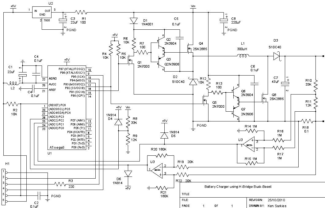
The buck-boost converter is valuable when the output and/or input voltages fluctuate significantly, necessitating the use of a buck converter at times and a boost converter at others. An example, which will be elaborated on in a future project,...
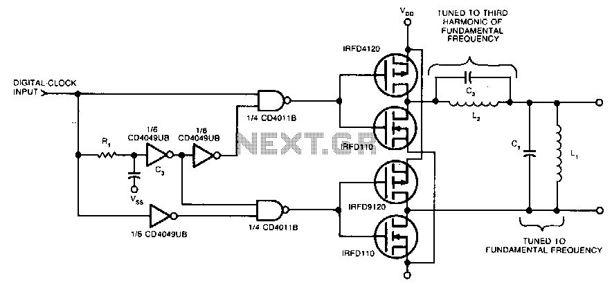
Two pairs of MOSFETs create a bridge that alternately switches current in opposite directions. Two parallel-resonant LC circuits complete the converter. The L1/C1 combination is resonant at the fundamental frequency, while the L2/C2 combination resonates at the third harmonic...
This inverter circuit can provide up to 800mA of 12V power from a 6V supply. For example, you could run 12V car accessories in a 6V car. The circuit is simple, about 75% efficient and quite useful. By changing...