
voltage converter circuit diagram

To convert a 60 Hz power supply to a 50 Hz output in a substation, a frequency converter is required. The frequency converter typically consists of a rectifier, a DC link, and an inverter. The rectifier converts the 60 Hz AC input voltage to a DC voltage. The DC link stabilizes the voltage and allows energy storage, which can help in maintaining a steady output during fluctuations. Finally, the inverter converts the DC voltage back to AC at the desired frequency, which in this case is 50 Hz.
The schematic for the substation would include the following key components:
1. **Input Transformer**: The input transformer steps down the 132 kV supply to a more manageable voltage level suitable for the rectifier. It is crucial to select a transformer that can handle the power requirements of 100 MVA.
2. **Rectifier**: A three-phase diode bridge rectifier is commonly used for converting the AC input (60 Hz) to DC. This component must be rated for the maximum current and voltage expected from the transformer output.
3. **DC Link**: This section typically includes capacitors to smooth the DC voltage output from the rectifier. The capacitance value should be calculated based on the load requirements and expected ripple voltage.
4. **Inverter**: The inverter is responsible for converting the DC voltage back to AC at 50 Hz. A PWM (Pulse Width Modulation) inverter is often employed for this purpose, providing better control over the output waveform and allowing for more efficient operation.
5. **Output Transformer**: After the inverter, an output transformer may be used to step up the voltage back to 132 kV, if necessary, for distribution purposes.
6. **Control System**: A control system is essential for managing the operation of the frequency converter, ensuring synchronization between the input and output, and providing protection against faults.
7. **Wiring Diagram**: The wiring diagram should clearly illustrate the connections between these components, including the input and output terminals, grounding points, and any necessary protection devices such as circuit breakers or fuses.
This comprehensive approach ensures that the substation can efficiently convert the frequency from 60 Hz to 50 Hz while maintaining the required power output of 100 MVA. Proper attention to component ratings and system design will be crucial for reliable operation.A substation capable of consuming 100MVA with375KVA, 60Hz in input and 132KV and 50hz using same power. so my problem is how to change the 60hz to 50hz, including wiring diagram 🔗 External reference
Related Circuits
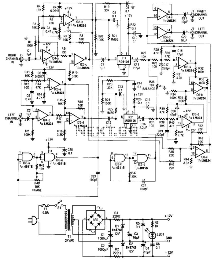
Right- and left-channel signals pass through buffer amplifiers C4-a and C4-b into the active crossover IG5. Low frequencies are directed to mixer IC6-c, while middle and high frequencies are sent to analog delay lines 1C1 and 1C2. The output...
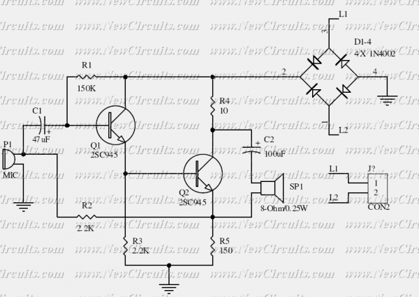
This is the basis of electronics telephone sets. You can use it to replace the talking circuit of an old telephone set with new design, better noise rejection and reliability one. Also you can use it to build a...
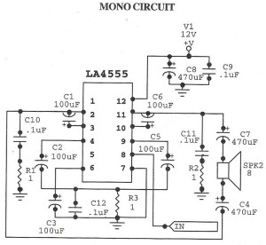
The following circuit illustrates an audio amplifier mono circuit diagram. This circuit is based on the LA4555 integrated circuit (IC). Features include a mono configuration and a power output of 2.3 watts. The audio amplifier circuit utilizing the LA4555 IC...
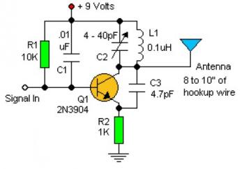
Experimenting with the size of the coil and the number of turns can influence the frequency and signal output of the oscillator. The signal can be received using a standard FM radio receiver. The input signal should be coupled...
This is a range of IF signal circuits that may be of interest to radio hobbyists and professionals alike. Transistors T1 and T2 form an astable multivibrator oscillating in the audio frequency range of 1 to 2 kHz. An...
The following circuit is an example of how to get power from an RS-232 serial port. It provides regulated +5V power for logic circuits and also unregulated positive and negative power supplies for the RS-232 transmitting circuit. The circuit...