
A Dual Temperature Display With Humidity Measurement

The thermometer circuit integrates several components to achieve accurate temperature and humidity measurements in both indoor and outdoor environments. The LM19 temperature sensor is a precision analog device that outputs a voltage proportional to the temperature, which is read by the ATmega328 microcontroller through one of its analog input pins. This microcontroller, a member of the popular AVR family, is programmed to process the analog signal and convert it into a digital temperature reading.
For indoor measurements, the SHT21 sensor provides both temperature and humidity data via the I2C communication protocol. The use of the PCA9517 level translator is crucial for ensuring compatibility between the 5V logic of the microcontroller and the 3V logic of the SHT21. This component allows for bidirectional communication on the I2C bus while maintaining signal integrity, thus preventing data loss or corruption.
The physical layout of the circuit is designed for practicality and ease of use. The SHT21 sensor is mounted on a breakout board, which simplifies connections and allows for easy integration with the microcontroller. A short cable connects this breakout board to the main MCU board, ensuring minimal signal loss and interference. The LM19 sensor, protected by heat-shrinking tubing, is connected via a stereo cable, which is advantageous for long-distance applications. The cable can be extended to a maximum length of 30 feet, provided that the total load capacitance does not exceed 300pF, ensuring reliable performance in various environmental conditions.
Overall, this thermometer design effectively combines analog and digital sensing technologies, utilizing a robust microcontroller and appropriate interfacing techniques to deliver accurate and reliable temperature and humidity readings across a wide range of applications.This thermometer uses an LM19 sensor calibrated for measuring a wide temperature range (-55 130 Celsius, -67 266 Fahrenheit) for outdoor temperature measurement and an SHT21 digital thermometer with humidity measurement for indoor use. An ATmega328 microcontroller is used to read the temperatures from both an analog sensor LM19 using an analog input pin and a digital sensor
SHT21 using the I2C bus. Since SHT21 uses 3V logic while the rest of the circuit uses 5V logic, a voltage translation circuit is necessary to interface SHT21 with the MCU. I used Taxes Instruments s PCA9517 level-translating I2C bus repeater as the voltage level shifter. The voltage shifting circuit is shown below: The SHT21 sensor is mounted on a breakout board and connected to the MCU board via a short cable.
The LM19 sensor is encapsulated in a section of heat-shrinking tube and connected to the controller via a stereo cable. The cable length used can easily be extended to as long as 30 feet as long as the load capacitance is less than 300pF.
🔗 External reference
Related Circuits

The objective is to vary two voltages, V1 and V2, by an equal percentage of their respective ranges (V1MAX - V1MIN and V2MAX - V2MIN), where V1MAX, V1MIN, V2MAX, and V2MIN are independent of one another. A common approach...
The LED guard-rail tube, also known as the decorative tube, is an advanced LED illumination product designed for decorative purposes. It utilizes red, green, and blue LEDs as light sources, employing microelectronics and digital technology to create color chasing...
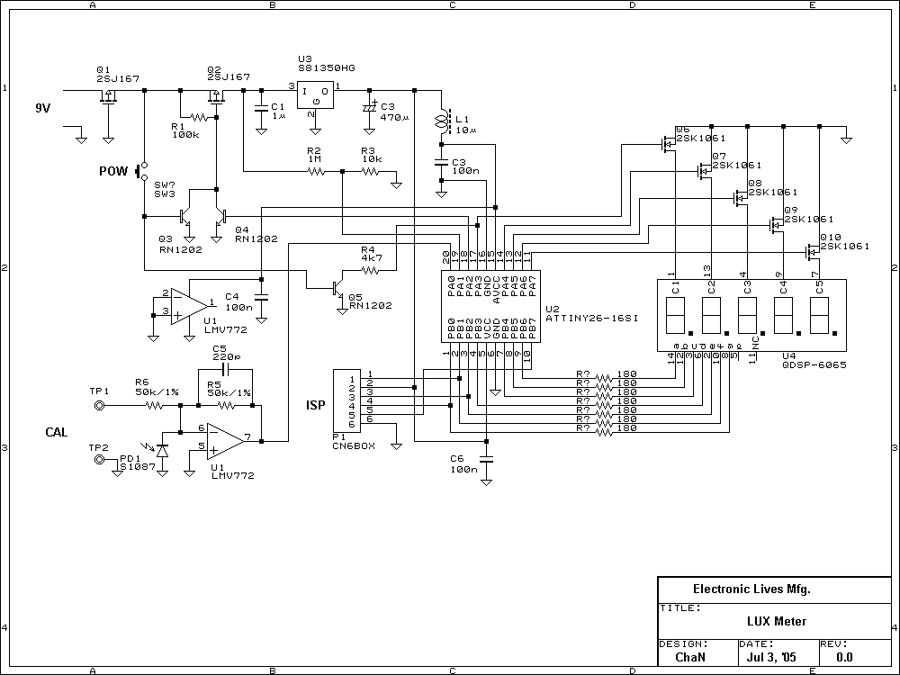
Lux meter circuit using an Atmel ATtiny26-16 microcontroller, which displays lux values on an LED display. The circuit utilizes 2SK1061 MOSFETs for driving the LEDs. The lux meter circuit operates by measuring ambient light levels and converting these measurements into...
An exhaust fan is a crucial component in kitchens. This document presents a simple circuit designed to control kitchen fans by monitoring the ambient temperature. It is built around... The circuit for controlling an exhaust fan based on ambient temperature...
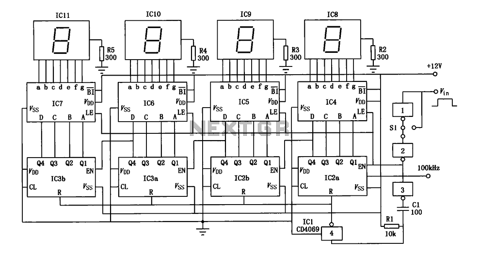
A digital pulse width measurement circuit is presented. It operates with a 100 kHz reference frequency to count the pulse width of the input signal. The count value represents the measured pulse width displayed on four seven-segment LED displays....
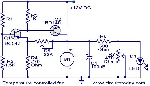
This circuit utilizes two transistors to regulate the speed of a 12 V DC fan based on temperature changes. A thermistor (R1) detects the temperature. As the temperature rises, the base current of transistor Q1 (BC 547) increases, leading...