
A Fluid Sensor

The circuit described is designed for measuring the resistance of conductive liquids, particularly useful in applications involving electrolytic solutions. The two parallel metal plates act as electrodes, with one potentially being the container itself, ensuring a robust and effective measurement environment. The choice of metal is critical, especially for applications involving acidic or alkaline solutions, as it must resist corrosion and maintain conductivity.
The operational amplifier Q1 serves as a voltage reference, stabilizing the circuit at approximately 4.75 volts. The transistor Q4 acts as a switch that engages when the base receives a signal of around 0.4 volts, allowing for precise control over the measurement process. The AC signal applied across the probes helps to mitigate any DC offset, which could lead to erroneous readings or unwanted electrochemical reactions, such as plating on the electrodes.
The resistance comparison between the liquid and the internal reference resistance RX is a pivotal aspect of this circuit. The RX resistor, typically set at 15K, can vary between 1K and 100K, depending on the specific application requirements. This flexibility allows the circuit to be tailored for different types of solutions and concentrations. The coupling capacitor of 0.047 µF plays a vital role in blocking DC voltage while allowing the AC signal to pass, thereby ensuring that the probes remain free of any unwanted buildup that could skew measurement results.
In addition to the LED and piezo speaker indicators, which provide visual and auditory feedback of the circuit's status, the option to incorporate a relay offers a method for controlling larger loads or interfacing with other systems. However, caution is advised when selecting components, particularly regarding the use of capacitors in conjunction with piezo devices, as they can restrict the desired frequency response.
In practical applications, the ability to calculate the resistance of various aqueous solutions based on electrode dimensions and spacing enhances the versatility of this circuit. This feature is particularly useful in laboratory settings, quality control processes, and environmental monitoring, where precise measurements of conductivity are essential for assessing solution properties and concentrations.For Conductive Liquids: These may simply consist of Two Parallel Metal Plates. If the Container is Metal, that could act as one of the plates. NOTE: A Suitable metal is required for Acid or Alkaline Solutions. The Emitter of Q1 is the circuits "Voltage Reference" (Aproximately 4. 75 volts) and the circuit switches when the Base of Q4 gets a signal of about 0. 4 Volts. When in use, an AC signal is passed through the liquid between the two probes. This detector than compares the fluids resistance to the internal resistance of RX. "CX", is Mainly used with Inductive Loads. On the Schematic it shows a Visual LED and a Pizo Speaker, But these could be replaced with a Relay. Note: Do NOT Use this Capacitor if using the Pizo Device or a Speaker. It Will Stop 4 to 5 Khz Frequency from coming through. "RX" Reference is typically 15K and it is coupled to a 0. 047 uF Cap. However it may be in a range from 1K to 100K. The. 047 capacitor is provided so there is no Net DC Voltage on the Probes. The use of an AC Signal also prevents any Plating effects from occuring on the probes. It is Possible to calculate the resistance of any aqueous solution of an electrolyte for different concentrations, Provided the dimensions of the electrodes and their spacing is known. 🔗 External reference
Related Circuits
This issue features articles on various measurement and sensor-related embedded design projects. Readers are encouraged to attempt similar projects and share their results. Starting on page 14, Petre Tzvetanov Petrov describes a multilevel audible logical probe design. Petrov notes...
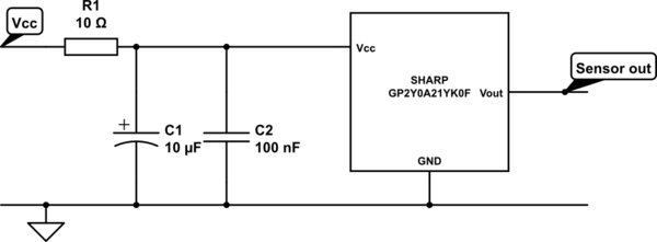
A project involves two distance sensors that signal an Arduino to operate a servo motor when an object comes within range. The system functions correctly; however, the sensors output a consistently high voltage, necessitating a high cutoff voltage in...
The provided schematic diagram illustrates an LM741 light/dark sensor circuit, derived from the 741 Op-Amp Tutorial by Tony van Roon. The ECG128/NTE128 transistor can be replaced with any NPN transistor that meets the necessary gain and current specifications for...
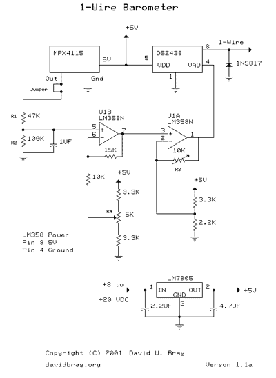
This design uses a Motorola MPX4115 Silicon Pressure Sensor, a Dallas Semiconductor DS2438 Smart Battery Monitor (to perform 1-Wire analog to digital conversion), an operational amplifier, a voltage regulator, a diode, and several resistors and capacitors. The circuit requires...
For proper operation, the circuit ground must be connected through a small-value, high-voltage-rated capacitor to one side of the mains supply socket. The "Live" side is the right one. This circuit is designed to animate shop windows using a...
Install the PIR module hanging from a 3-meter high mast to cover a 10-meter radius area. Connect its supply and relay terminals to the finished and enclosed circuit, ensuring the correct polarity is observed. A 4-core screened cable can...