
Capacitance multiplier

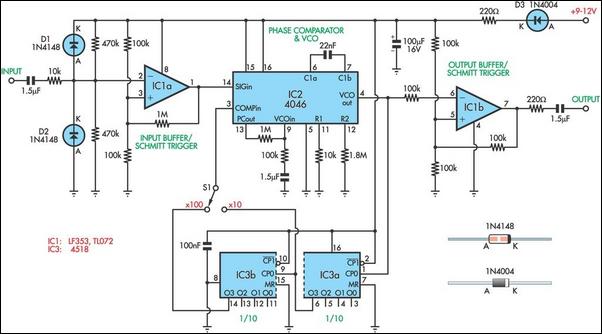
This circuit design leverages the principle of capacitance simulation through the use of smaller capacitors to achieve a much larger effective capacitance. By connecting multiple capacitors in a specific configuration, it is possible to create an equivalent capacitance that greatly exceeds the individual capacitor values. In this instance, using a capacitor of 10 µF, the circuit is able to simulate an effective capacitance of 10,000 µF.
The effective capacitance can be achieved by employing a network of capacitors in parallel or series, depending on the desired characteristics. In this scenario, the effective series resistance (ESR) plays a critical role in determining the performance of the circuit. A lower ESR will result in a higher quality factor (Q), which is essential for applications requiring efficient energy storage and minimal power loss.
To optimize the performance of the circuit, it is advisable to select the resistor Rl to be as large as practical. This will help minimize the impact of the effective series resistance on the overall performance of the capacitance simulation. The choice of resistor value should take into consideration the specific application requirements, including the frequency of operation and the load conditions.
In summary, this circuit effectively demonstrates how to simulate large capacitances using smaller components, providing a practical solution for applications that require high capacitance values without the need for physically large capacitors. The careful selection of component values and configuration is key to achieving the desired performance characteristics.This circuit can be used to simulate large capacitances using small value components. With the values shown and C = 10 µf, an effective capacitance of 10,000 µf was obtained. The Q available is limited by the effective series resistance So Rl should be as large as practical.
Related Circuits
This is a voltage multiplier circuit. The first circuit is used to double a square wave (of any amplitude). However, there is a drawback of approximately 2V losses in the base-emitter. A voltage multiplier circuit is designed to increase the...
This series-feedback configuration of compounds provides a high input impedance and stable, wide-band gain video amplifier suitable for general-purpose applications. It features low capacitance and high impedance. The described video amplifier circuit utilizes a series-feedback topology to achieve high input...
When designing bass reflex loudspeaker cabinets, it is essential to measure the speaker's resonance with an accuracy of approximately 1%. This requires an audio oscillator and a frequency counter. However, the accuracy and resolution of a frequency counter when...
Common emitter amplifier circuit with resistance and capacitance coupling. The common emitter amplifier circuit is a fundamental configuration in analog electronics, widely utilized for its ability to amplify voltage signals. This circuit employs a bipolar junction transistor (BJT) as the...
These are circuits of high impedance low capacitance buffer and high impedance low capacitance amplifier. The first figure is a high impedance low capacitance. High impedance low capacitance circuits are critical in various electronic applications, particularly in signal processing and...
If this picture above looks a lot like the Pretty Good LC Meter also on this web site, that's because it's the same meter, but with some significant improvements. At this point, it's a good idea to read the...