
A Friendly Charger Schematic for Mobile Phones

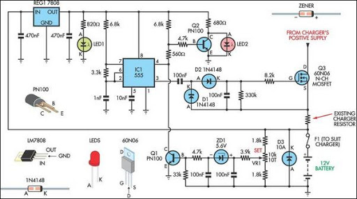
The described circuit functions as a mobile phone charger designed to safeguard the device from voltage spikes and short circuits. In typical scenarios, many standard mobile chargers lack adequate current and voltage regulation, which can lead to potential damage to the mobile phone's internal components.
This charger incorporates essential protective features. The voltage spike protection is typically achieved through the integration of transient voltage suppression (TVS) diodes or varistors, which divert excess voltage away from the device. This mechanism ensures that any sudden surges in voltage do not reach the mobile phone, thereby preserving its functionality and longevity.
Additionally, short-circuit protection is a critical feature that prevents excessive current flow that could otherwise lead to overheating or damage. This is often implemented using a current sensing circuit that detects abnormal current levels and automatically disconnects the charger from the power source. This disconnection can be accomplished through a relay or a MOSFET switch, which acts to open the circuit in the event of a detected fault.
Current and voltage regulation can be achieved using linear regulators or switching regulators, depending on the desired efficiency and thermal performance. Linear regulators provide a simple solution with low noise, while switching regulators can offer higher efficiency, especially in battery-powered applications.
In summary, the charger is equipped with protective measures against voltage spikes and short circuits, while also ensuring stable current and voltage regulation. This design not only enhances the safety of the mobile phone during charging but also contributes to the overall reliability and performance of the device.Charges and protects your mobile phone from voltage spikes and short-circuit Most mobile chargers do not have current/voltage regulation or short-circuit.. 🔗 External reference
Related Circuits

This optodetector measures the position of the ball by the amount of light transmitted by the infrared LED. It generates a linear signal across the small area of the detector, rather than simply providing an "on" or "off" output....

This circuit was designed to control power delivery to a Peltier cooler in a vehicle. The power to the load from the vehicle's battery is managed by a Single Pole Double Throw (SPDT) relay. The circuit utilizes an SPDT relay...
This circuit is intended for charging lead-acid batteries with a solar panel. The customary diode that prevents the battery from discharging through the solar panel has been replaced by a FET-comparator combination. The charger will stop charging once a...
This circuit serves as a standard battery charger and is specifically designed to maintain a 12-Volt Lead-Acid Battery, such as those used in flight boxes, in an optimal charged state. It is important to note that this circuit is...
Most off-the-shelf car battery chargers cannot be left connected to the battery for long periods of time as overcharging can cause battery damage. The operation of car battery chargers typically involves converting alternating current (AC) from a wall outlet into...
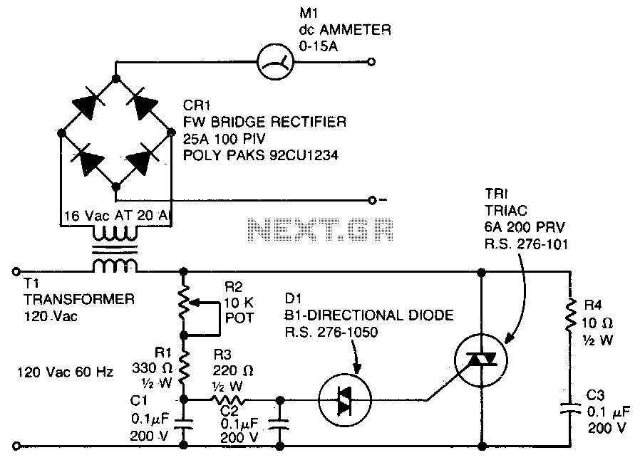
A diac is utilized in the gate circuit to enable operation for the signal applied to the gate. R1 sets a threshold level for triggering the triac. C3 and R4 are chosen to restrict the maximum charging current, forming...