
A multi-purpose radio talk lamp circuit

The Ai. A2 series circuit is designed to interface with a telephone line, enabling it to respond to specific events such as off-hook conditions or sound anomalies. The core functionality is initiated when an off-hook current flows through a light-emitting arc tube, which activates a photosensitive MOSFET. This MOSFET is critical for detecting the light levels and controlling the subsequent actions of the circuit.
In the initial stage, the circuit detects the off-hook condition via a saturated base voltage, which allows for the conduction of current through the base of the MOSFET. This current generates a negative pulse sent to an integrated circuit (IC), which temporarily flips its state and outputs a high signal at pin 3. This output serves as a trigger for the lamp circuit, illuminating lamp H.
Following the completion of the call, the circuit is designed to reset itself. The delay mechanism, formed by capacitors (C1) and resistors (R), allows lamp H to remain lit for a predetermined duration of approximately 45 seconds after the call ends. This delay is essential for providing visual feedback to the user.
Moreover, the circuit incorporates a light control feature, which ensures that lamp H only activates in low-light conditions. This is achieved through the use of a light-sensitive component (MG), which detects ambient light levels. When sufficient light is present, the resistance within the circuit increases, reducing the bias at the base of the MOSFET and effectively turning off the lamp. This ensures energy efficiency and prolongs the lifespan of the lamp by preventing unnecessary illumination during daylight.
The arrangement of resistors and tuning components within the trigger circuit is designed to modulate the conduction angle of a silicon-controlled rectifier (SCR). This modulation allows for smooth and controlled lighting of lamp H, adapting to different operational conditions, such as ringing or off-hook scenarios. The entire system is powered through an AC supply, ensuring that lamp H remains non-operational when disconnected from power, thereby enhancing safety and preventing accidental illumination.
In summary, the Ai. A2 series circuit provides a robust solution for telephone line indication, combining responsive light control with an effective delay mechanism to enhance user experience while maintaining energy efficiency.Ai. A2 series with the telephone line, when the sound wrong or off-hook current is passed lC, inside the arc tube made of light so wins the photosensitive MOSFET, VT J withdraw al base voltage saturated conduction, to one-shot IC: (2) feet away negative pulse, IC2 flip temporarily into the love, (3) pin output high. vs current turn trigger pole eligible uov cross flow circuit, lighting the lamp H. After the call to the telephone hook-shaped lamp circuit before recovery, due IC, (6). (7) feet to eight and Cl as the composition of the extension js circuit, after each hanging lamp H may delay self-extinguish after 45 seconds.
The principle above when the lamp for the delay. The circuit consists of MG. RP composed of light control circuit, has its day or indoor illumination light it. Because hidden in the next sequence by MG lamp light pierced by light irradiation was within the low resistance, so that the base bias VT Heron reduced even Icl conducting work, V7 remains off like blogs, according to ten circuit does not work, the lamp H is not bright only when there is no light at night and IJ was lit. Circuit arrangement of felt, R, tnr tune trigger circuit, pupa section vs SCR conduction angle, so that the lamp flat lighting is used for wither.
Like two trigger, ringing or off-hook telephone lamp circuits operate normally I do with u inch a IF, D instructions, usually connected to the AC power supply circuit, no power lamp H does not shine, do not l Shu barrel of light light switch, lamp Ge can simply tune out the lights.
Related Circuits

The complete electrical circuit diagram of a line follower robot is based on the ATmega16 microcontroller. This robot consists of three primary modules: the sensor module, the microcontroller module, and the DC motor module. A comprehensive tutorial, including circuit...
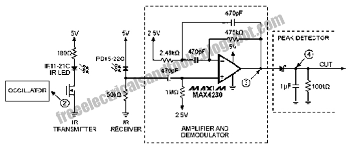
The following circuit illustrates an Infrared Proximity Sensor Circuit Diagram. This circuit is based on the MAX4230 integrated circuit. Features include a 10 kHz oscillator. The Infrared Proximity Sensor Circuit utilizing the MAX4230 integrated circuit is designed to detect the...
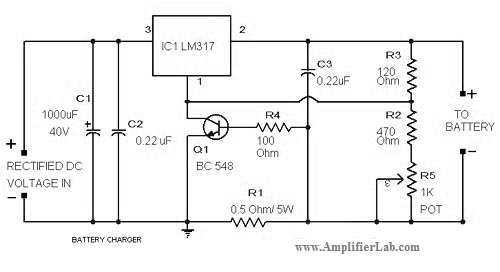
The circuit diagram of a lead-acid battery charger is presented here. The main component of this circuit is the IC LM317. The lead-acid battery charger circuit utilizing the LM317 voltage regulator is designed to efficiently charge lead-acid batteries while providing...
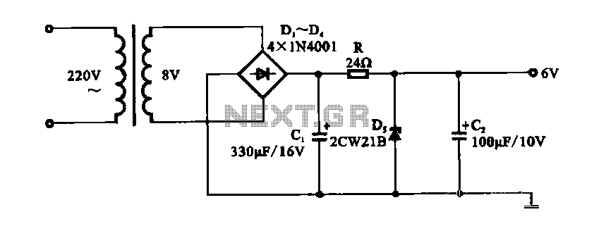
A DC shunt regulator power supply circuit is presented, which operates in parallel with a radio circuit. The circuit begins with an AC voltage of 22V, which is stepped down to 8V using a transformer. The 8V AC voltage...

The LM4844 is an integrated audio subsystem designed for stereo cell phone applications. Operating on a 3.3V supply, it combines a stereo speaker amplifier delivering 495mW per channel into an 8Ω load and a stereo OCL headphone amplifier delivering...
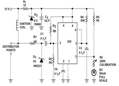
The sections available in this datasheet cover general design considerations for the 555 timer, frequently asked application questions (FAQ), design formulas, and examples of innovative applications. Examples of applications include a Missing Pulse Detector, Pulse Width Modulation (PWM), Tone...