
A one-touch bedside lamp dimmer circuit

The circuit operates as a dimming control system using a combination of photoelectric sensors and silicon-controlled rectifiers (SCRs). The training device is designed to demonstrate the principles of electronic control and automation. The trigger terminal CI serves as the primary input point where a positive voltage pulse initiates the operation. The buck converter reduces the voltage while maintaining current, ensuring that the circuit operates efficiently without exceeding component ratings.
The Johnson photovoltaic tip tuner functions as a variable resistor that adjusts the input signal based on the light detected by the photoelectric sensor. When light intensity changes, the output level adjusts in real-time, allowing for dynamic control of the connected load, such as a light bulb. The BCR's conduction angle is crucial for controlling how much current flows through the load, which directly affects the brightness of the light bulb.
The inclusion of the wind-blocking diode protects the circuit from voltage spikes and ensures stable operation. The system's design allows for easy integration into various applications, including educational demonstrations and practical training in electronic control systems. The button that generates sharp pulse peaks is a critical component, as it initiates the counting process in the TC meter, providing visual feedback on the operation of the circuit.
In summary, the described training device serves as an effective tool for illustrating the functionality of electronic components and their interactions within a control system. The design emphasizes efficiency, safety, and adaptability, making it suitable for various educational and practical applications in the field of electronics.1C foot VIII made a number of training device, from the trigger terminal CI. f-off positive input pulse. End by supporting a n quotient output level. Lose. commercial electric F via electrical VflR, - Rn buck, limiting evacuation Johnson photovoltaic tip tuner PC input - end. When the signal input of the photoelectric oval table varies, the output side of the output with the input and change the situation number of call control signal, government intelligence No. 4 Polo made a direct trigger orientation, swollen silicon BCR. He H has a conduction angle, from the state of the cylinder contained bulb H county corresponding operating voltage.
Reasonable withered section R: - Rb resistance, can change the trigger enjoin strength, and then the coup BCR conduction angle, so that the rate which kept the lamp voltage end changes reach Xie s mouth. I - a wind blocking diode. Convex on the 1st .VD Xiamen Island crucible for the 22clV City in galvanic becomes 9V DC voltage dimming circuit for making J express.
S Hungary button, click S.9V straight hatred electricity, k through a, Ma San generate servant JI. sharp pulse peaks for the CL H] r ic end, triggering TC meter teach each press FS, mcc input count pulse number situation, light bulbs child width will change with porphyrin gear. verandah with output sequence sequentially changed consultation (or darken) when making contact S h lC end of island electricity, F after two pull tube Eritrea is fed to the complex Cr his side.
forced to make baby complexification., I end as silk electric tfi, YZ - y side are almost low, lights off II (y terminal of the power is not connected. Road ashamed to supply frog Andean block.).
Related Circuits
This is a single alarm circuit. The circuit includes automatic exit and entry delays, a timed bell cut-off, and a system reset. It has provisions for normally open and normally closed inputs. The single alarm circuit is designed to provide...
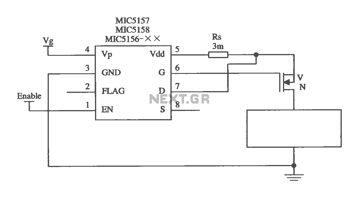
The MIC5156 is a device that incorporates a current limiting function, allowing it to handle high output currents. It can operate with or without a switching regulator circuit. The S terminal is left vacant, and a 16V Zener diode...
The liquid level controller circuit comprises a power supply circuit and a level detection control circuit, as illustrated in the accompanying chart. The power supply circuit includes a power switch (S1), a power transformer (T), bridge rectifiers (UR1, UR2),...
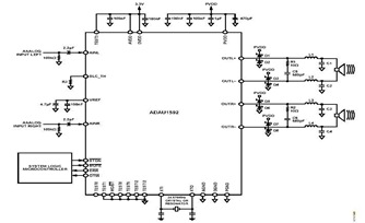
This is a typical stereo application circuit schematic of the ADAU1592, a 2-channel, bridge-tied load (BTL) switching audio power amplifier. The ADAU1592 can be utilized in flat panel televisions, PC audio systems, and mini-component applications. The ADAU1592 is designed to...
LED sequencer that follows the rhythm of music or speech, powered by a 9V battery, is a portable unit. The basic circuit illuminates up to ten LEDs in sequence, following the beat. The LED sequencer circuit operates by detecting audio...
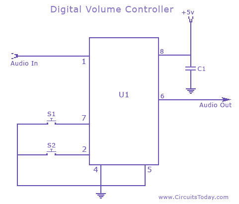
A digital volume control circuit diagram utilizing the DS1669, a potentiometer integrated circuit. This circuit can serve as a digital volume controller for audio amplifiers and various other applications. The digital volume control circuit employs the DS1669 integrated circuit, which...