
A Repeating Timer Circuit No.7

The monostable timer circuit is structured to provide a reliable timing function by utilizing a combination of resistors and capacitors to create the desired ON and OFF periods. The circuit is built around a timing IC, typically a 555 timer in monostable mode, which is triggered by a low pulse to start the timing cycle. Upon triggering, the output goes high, energizing the relay and initiating the timing sequence. The time duration during which the relay remains activated is determined by the formula T = 1.1 * R * C, where T is the time in seconds, R is the resistance in ohms, and C is the capacitance in farads.
In practical applications, the choice of R3 and C2 will dictate the ON time, while R4 and C3 will control the OFF time. Adjustments can be made to these components to fine-tune the timing as needed. For instance, a larger capacitor or resistor will increase the time period, while a smaller value will decrease it. The circuit should be designed with adequate space to accommodate the components, ensuring that they are securely mounted and that there is no risk of short circuits.
Safety precautions must be observed when dealing with mains voltage. It is advisable to use a relay rated for the voltage and current levels of the load being switched. Additionally, incorporating isolation techniques, such as opto-isolators or separate power supplies for the low-voltage control circuit and the high-voltage load, can enhance safety and reliability.
The circuit board layout should be designed to minimize interference and ensure proper operation of the timer. Ground planes and proper routing of signal paths are essential to reduce noise and improve performance. The use of decoupling capacitors near the IC can also help stabilize the power supply and improve timing accuracy.
Overall, this monostable timer circuit offers flexibility and adaptability for various timing applications, making it a valuable tool in electronic design and automation tasks.This timer is based on a simple Monostable Circuit. The length of time the relay remains energized - the ON period - is controlled by the values of R3 & C2. And the length of time the relay remains de-energized - the OFF period - is controlled by the values of R4 & C3.
With the component values shown - periods of up to 30 minutes are available. T he length of time the relay remains energized is controlled by the values of R3 & C2. And the length of the time the relay remains de-energized is controlled by the values of R4 & C3. Owing to manufacturing tolerances - the precise length of the time periods available depends on the characteristics of the actual components you`ve used. You can choose component values that suit your own requirements. You should get about 70 seconds for every 1Meg/100uF. So 4M7 & 100uF will give about 6 minutes. And 4M7 & 1000uF will give about an hour. If your time periods don`t need to be too precise - and more-or-less is close enough - you can replace the pots with fixed resistors.
Do not use the "on-board" relay to switch mains voltage. The board`s layout does not offer sufficient isolation between the relay contacts and the low-voltage components. If you want to switch mains voltage - mount a suitably rated relay somewhere safe - Away From The Board.
I`ve used a SPCO/SPDT relay - but you can use a multi-pole relay if it suits your application. The timer is designed for a 12-volt power supply. However - it will work at anything from 5 to 15-volts. All you need do is select a relay to suit your supply voltage. The Support Material for this circuit includes a step-by-step guide to the construction of the circuit-board - a parts list - a detailed circuit description - and more. 🔗 External reference
Related Circuits
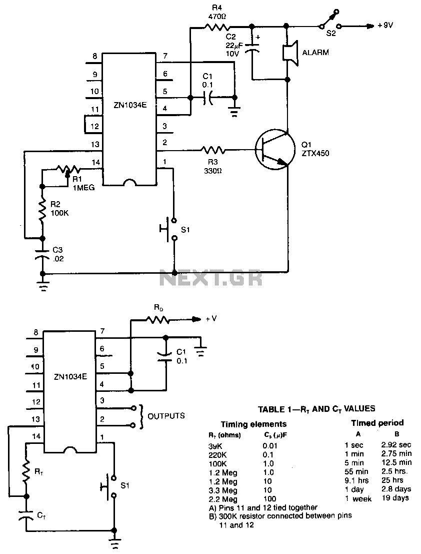
When used as a stand-alone device, the ZN1034E from Ferranti can provide timed intervals ranging from 1 second to 19 days, although the RC time constant is only 220 seconds. The ZN1034E includes an internal voltage regulator, an oscillator,...
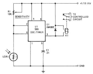
The following circuit illustrates a Photo Alarm Electronic Circuit. This circuit is based on the 555 Timer IC and incorporates features such as an LDR (light-dependent resistor). The Photo Alarm Electronic Circuit utilizes a 555 Timer IC configured in monostable...
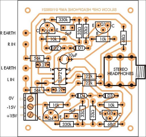
In addition to its primary function as a headphone amplifier, this circuit can be utilized for various applications requiring a wide bandwidth low-power amplifier. It is designed around an operational amplifier (op-amp), with its output current enhanced by a...
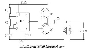
The timer IC (NE555) is configured as an astable multivibrator in this circuit. It generates an alternating non-sinusoidal output waveform as soon as a supply voltage of 12V is applied. Therefore, alternating voltage is produced from direct current (battery)....

A simple battery charger designed for Nickel Metal Hydride batteries that require current-regulated charging. The charger delivers a charging current of 140 mA for efficient battery charging. The power supply section includes a 0-18 volt AC 1 Ampere step-down...
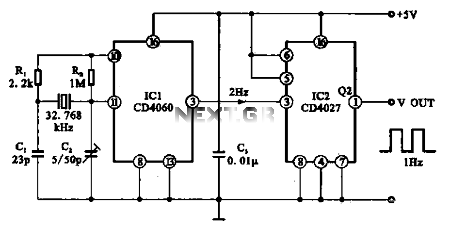
A 1Hz clock signal generator circuit is presented, which demonstrates a sophisticated clock signal generating mechanism. This circuit can be utilized for digital clocks and timing applications. It comprises a binary counter (CD4060), a JK flip-flop (CD4027), and a...