
SIMPLE INVERTER CIRCUIT 230V

The NE555 timer, when configured in the astable mode, operates continuously without any external triggering. It alternates between its high and low states, producing a square wave output. In this circuit, the frequency and duty cycle of the output waveform can be adjusted by changing the values of the timing resistors and capacitor connected to the NE555. The output frequency can be calculated using the formula:
\[ f = \frac{1.44}{(R1 + 2R2)C} \]
Where \( R1 \) and \( R2 \) are the resistances in ohms, and \( C \) is the capacitance in farads. This output is a square wave, which is suitable for driving a transformer.
The transistors in the circuit act as switches, amplifying the output from the NE555 timer to a level sufficient to drive the primary winding of the step-up transformer. When the transistors are turned on by the NE555 output, they allow current to flow through the primary winding of the transformer, inducing a higher voltage in the secondary winding due to the transformer's turns ratio.
The step-up transformer is critical in converting the low voltage (12V) output from the circuit to a higher voltage level (230V) suitable for various applications, such as powering AC devices. The transformer must be rated appropriately to handle the power requirements and ensure safe operation.
Overall, this circuit effectively demonstrates the conversion of direct current into a higher alternating voltage using a timer IC, transistors, and a step-up transformer, making it a valuable design for applications requiring voltage amplification.The timer IC(NE555) is wired as an ASTABLE MULTIVIBRATOR in this circuit. It will generate Alternating non sinusoidal output wave form at the instant we giving supply Voltage(12V). Thus primarily we generated Alternating Voltage from direct Current (Battery). The output from these transistors are again fed to the input(primary) of a Stepup Transformer. This will upconvert the input Voltage to desired level (230V). 🔗 External reference
Related Circuits
A long time ago, when telephones were simple and reliable from an electrical standpoint, telecom operators installed surge protection on all telephone lines at risk from storms. Paradoxically, as modern technology has led to the use of delicate and...
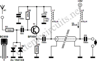
Function: step down the antenna impedance from high to 50 ohms and not, as would be expected, to effect a change from balanced to unbalanced. Component: .. In the context of antenna systems, impedance matching is crucial for maximizing power...
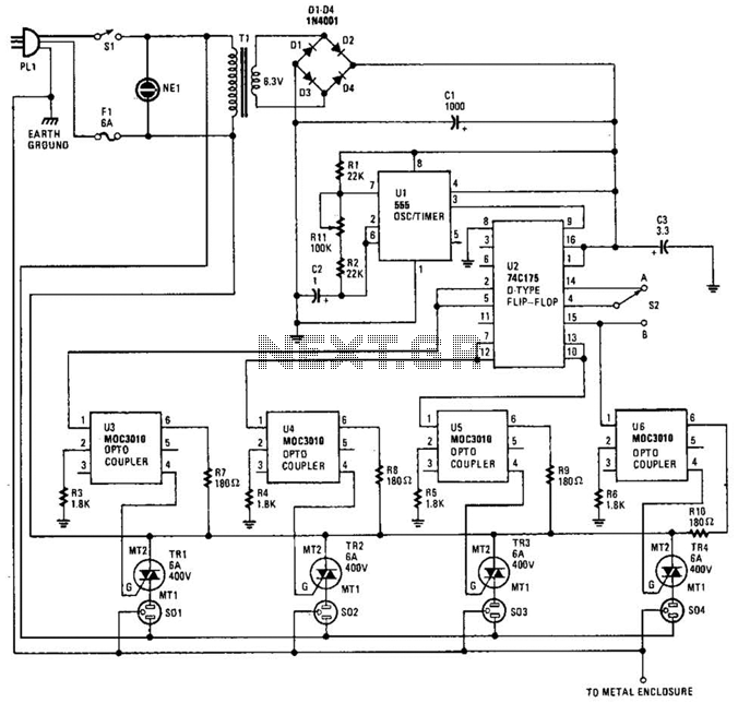
The integrated circuit U1 (a 555 oscillator/timer) is configured as a conventional pulse generator. The frequency of the pulse generator is adjusted using potentiometer R11. Resistor R2 limits the maximum frequency attainable. The output from the pulse generator is...
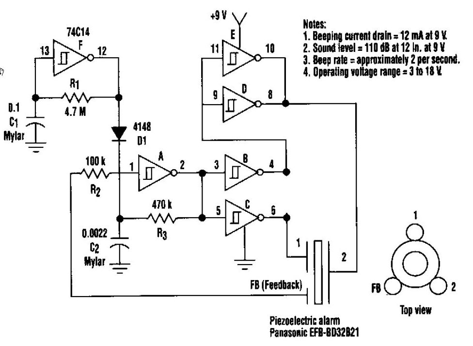
This beeper circuit generates an impressive 110dB sound level from a 9V supply. The design employs a single 74C14 (CD40106B) CMOS hex inverting Schmitt-trigger integrated circuit (IC), which must be paired with a piezoelectric device featuring a feedback terminal....
IR appliances use pulses (control signals) sent over a modulated IR carrier wave. The carrier wave may be modulated at various frequencies, 36-38KHz being the most popular. Some Satellite receivers use even higher frequencies than this. The IR1 remote...
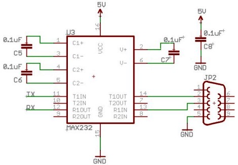
Select a free schematic drawing software that resembles the two mentioned. There have been discussions regarding circuit drawing software. Fritzing is favored, although it lacks certain components, such as the RS232 component. There is a request for feedback on...