
A SHORT WAVE REGENERATIVE RECEIVER

The Colpitts regenerative receiver described offers a practical solution for shortwave enthusiasts seeking a cost-effective alternative to commercial receivers. The use of a single set of coils for tuning across a wide frequency range simplifies construction and enhances usability. The circuit's reliance on a common-collector configuration allows for efficient amplification while maintaining high sensitivity, crucial for receiving weak signals in crowded frequency bands. The implementation of a vernier-type variable capacitor aids in fine-tuning, a necessary feature for effective operation in the shortwave spectrum, where signal overlap is common.
The audio amplification stage, employing transistors Q2 and Q3, ensures that the output is sufficiently robust for various listening devices, accommodating both high-impedance earphones and low-impedance headphones. The inclusion of a volume control allows users to customize their listening experience, catering to different environments and preferences.
The pseudo tuning-indicator circuit enhances user experience by providing visual feedback on signal strength, aiding in the tuning process. This feature is particularly beneficial for users who may not have extensive experience with shortwave radios, as it simplifies the process of finding and locking onto desired signals.
Overall, this Colpitts regenerative receiver design exemplifies a balance between simplicity, performance, and affordability, making it an attractive option for hobbyists and shortwave radio enthusiasts alike. The careful consideration of component selection and circuit design principles ensures that the receiver operates effectively across a wide range of frequencies while remaining user-friendly.Sensitivity and selectivity are issues that will invariably concern a short wave listener when he wishes to purchase a new receiver. Commercially available communications equipment will undoubtedly fulfill his expectations, but we are talking here of highly priced products.
Low-cost alternatives call mainly for homebrewed radios, and in this sense , the regenerative receiver is the common choice due to its simplicity, low parts count and very acceptable performance. The author is also a short wave enthusiast and for some time used his family`s Philips MW/SW vacuum tube radio.
Later, he changed to a solid-state Sony ICF-7600, a high selectivity receiver featuring ceramic filters in the IF stages. Then he would discover how much fun he could have building radios on his spare time. After testing a variety of schematics available in books and on the web, the author finally decided to make his own designs.
Back in 2003, an experimental Colpitts-type shortwave regenerative receiver was made public on the web by this servant. It was reported to tune from the 22-meter band up to the 11-meter band with a single set of coils. Operation was found to be satisfactory with the prototype built on a protoboard and a ground plane fixed underneath.
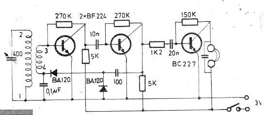
Further work with the receiver using different sets of coils revealed a larger usable frequency spectrum. Fig. 1 shows the schematic diagram of an improved version of the early receiver. It will tune signals from 3500kHz up to 26MHz, roughly in three bands, each with a 1. 96:1 frequency-ratio. It must be quoted that the said frequency ratio is what the author got for his prototype. It is a function of the maximum-to-minimum capacitance of the variable tuning capacitor and the stray capacitance of the circuit layout.
The Colpitts approach uses no tickler coil nor throttle capacitor for regeneration, as opposed to the Armstrong circuit. In our case, it resorts to transistor Q1`s base-emitter input capacitance and NPO-type ceramic capacitor C2 to effect the correct impedance transformation and phase shift necessary for regeneration to take place.
Q1 is the amplifier-detector and along with its associated circuitry forms the common-collector Colpitts regenerative amplifier, with R9 as the reaction control. The oscillating mode is employed when copying CW or SSB, otherwise, the stage should be left very near the threshold of oscillation for maximum sensitivity and selectivity.
It is best that the 100-pF variable capacitor C1 be a vernier type. It will help a lot when tuning-in the crowded SW bands. Q2 and Q3 form a high gain audio amplifier and ample volume should be expected at the output. This is why a volume control has been included in the circuit. A high-impedance crystal or ceramic piezoelectric earphone should be used for listening. Alternatively, an audio output transformer that will match low-impedance magnetic earpieces to 5kohms to 7kohms may be connected to Q3`s collector through a 0. 47-uF capacitor. High-impedance 2k-ohms magnetic headphones do not require a transformer. They can be connected directly to Q3`s output using the said capacitor. Components C9, R11, R12 germanium diode 1N34 (it can be any other germanium detector type), Q4, the S-meter and the high-efficiency blue LED form a pseudo "tuning-indicator" circuit which gives an idea of the available audio level at the output of Q3 after demodulation.
We have then a visual relative indication of the tuning action of our circuit. Solderless breadboards known as "protoboards" show parasitic capacitances of about 3pF between adjacent connection lines. Hence, excercising the builder some minimum of care in point-to-point connections on the layout, the protoboard will lend itself as an acceptable breadboarding material for the testing of simple receivers, such as the one dealt with here.
The author has tested on a breadboard of this sort the design herein described, with an addi 🔗 External reference
Related Circuits
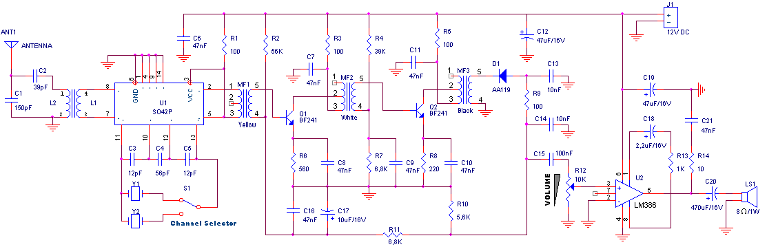
Oscillating circuits (coils) are constructed on a ferrite bar. For long wave reception, winding "1-2" consists of 135 turns, while winding "3-4" has 20 turns. For medium wave reception, winding "1-2" has 75 turns, and winding "3-4" has 7...
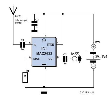
This is a preselector circuit designed for shortwave (SW) receivers, specifically a do-it-yourself (DIY) high-frequency preselector. The circuit employs a modern low-capacitance MOSFET with two gates, which generates a negative inverse reaction through an uncoupled source resistor. When applied...
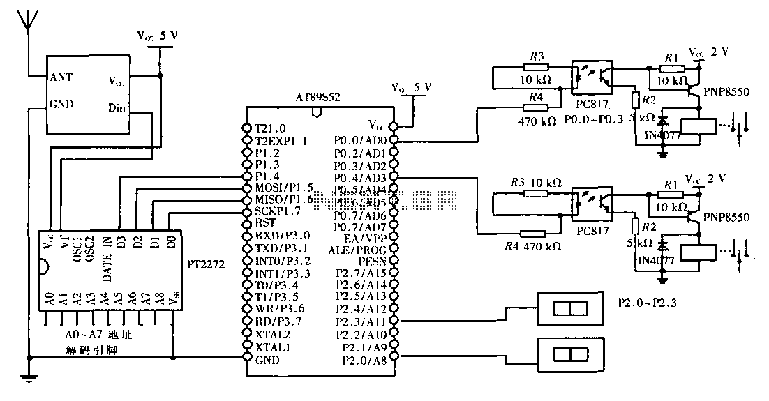
This design aims to create a long-distance wireless remote control switch lighting control system, which consists of a transmission system and a reception system. The system utilizes wireless transceiver modules for RF transmission and reception. The transmitting portion mainly...
For the regulation needs a transmitter or generator in mpa'nta the CB, that is to say in the region 27MHz. If you have a certain friend with CB, you convince you to help. Connect a piece of cable around...
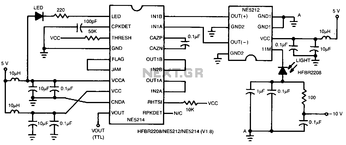
This two-chip receiver, designed for low-cost fiber optic applications at 100-M baud (50 MHz), features a minimal external component count. The receiver consists of pre-amplifier and post-amplifier integrated circuits (ICs) for enhanced stability. The preamplifier IC is characterized by...
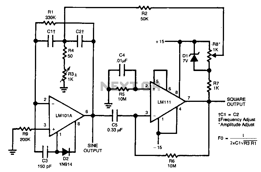
The circuit is designed to generate both sine and square wave outputs for frequencies ranging from below 20 Hz to above 20 kHz. The frequency of oscillation can be easily adjusted by modifying a single resistor, which is a...