
SW Receiver Preselector Circuit

This preselector circuit is particularly beneficial for enhancing the performance of shortwave receivers by filtering unwanted signals and improving selectivity. The use of a low-capacitance MOSFET allows for efficient signal processing while maintaining a high dynamic range, which is crucial for receiving weak signals in the presence of stronger ones. The design's ability to handle up to 2.5 Vpp input signals ensures that it can effectively manage strong incoming RF signals without distortion or overload, a common issue in many conventional receivers.
The adjustment capacitor C1 plays a pivotal role in tuning the circuit, allowing the operator to optimize the amplification based on the specific frequency being received. The LC network's resonance is critical in this regard, as it determines the frequency response and selectivity of the preselector. The six input coils, crafted with precision on high-quality ceramic cores, contribute to the circuit's overall performance by providing stable inductance values and minimizing losses.
Incorporating a ferrite bead at the gate terminal helps mitigate high-frequency noise and prevents unintended oscillations, which can degrade performance in sensitive RF applications. The output coil configuration, with its specific turn ratios, is designed to match the impedance of the subsequent stages effectively, ensuring maximum power transfer and minimal signal degradation. This comprehensive approach to circuit design makes the preselector an invaluable tool for radio amateurs seeking to enhance their shortwave receiver capabilities.This is a Preselector for SW receivers (diy hf preselector) circuit. The entry low capacitance of MOSFET modern, with two gates, will create negative inverse reaction through a uncoupled source resistor. Applied right this technique allows the creation of a entrance RF stage field with a relatively high dynamic range.
Radio amateur working on shor t wave: there is no need to tell, in the days of our times, the ability to face the signals of high level is a necessity for preventing overload of the receiver and intermodulations caused by very strong signals. Unlike of entry sections in many SW high quality receivers, this schematic has no difficulty in handling RF input signals up to 2.
5 Vvv. In this case we have 3Vvv on an impedance of 50 ©. Adjustment capacitor C1 determines the global amplification, which is mainly because because LC network resonance at the circuit input. The 6 entrance coils are coiled on ceramic dcores of very high quality with diameters of at least 10 mm.
Ferrite pearl is located right on the terminal gate 1 of T1, for a preventing parasites oscillations in the VHF and UHF bands. Output coil L7 is 20 turns (A) and 4 respectively turns (B) coiled on a ferrite core ring type G. 2-3/FT16. 🔗 External reference
Related Circuits
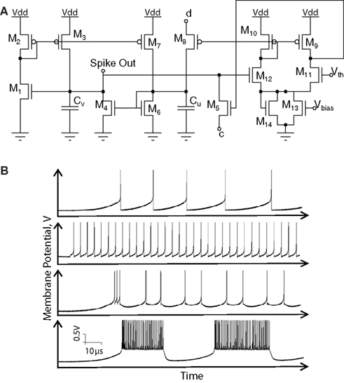
Hardware implementations of spiking neurons are highly beneficial for various applications, including high-speed modeling of large-scale neural systems, real-time operating systems, and bidirectional brain-machine interfaces. The specific circuit solutions for silicon neurons are dictated by the requirements of each...
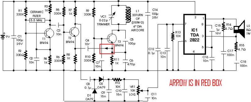
A schematic diagram for a metal detector has been found. The project does not need to be original and can be sourced from the internet. There are several questions regarding this schematic. One query pertains to a small arrow...
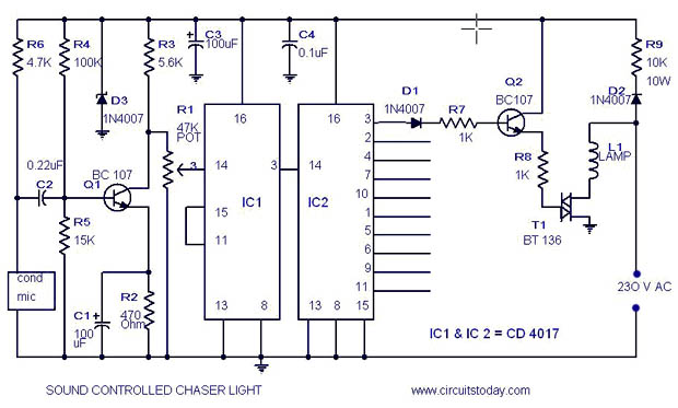
A simple musical light chaser circuit diagram and schematic using IC CD4016. This circuit blinks lights in response to sound, audio, or music output, causing 10 lights to dance according to sound frequency. The musical light chaser circuit utilizing the...
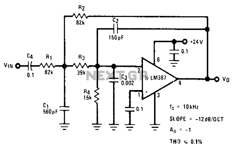
The circuit provides a passband gain of 1 with a corner frequency of 10 kHz, designed to eliminate high-frequency noise such as hiss, ticking, and popping sounds. This circuit operates as a low-pass filter, effectively attenuating frequencies above the specified...
This LED table or reading lamp circuit can be utilized for various applications, such as a reading lamp for a bed, a desktop or table lamp, a keyboard lamp (to illuminate the keys of a computer keyboard in low...
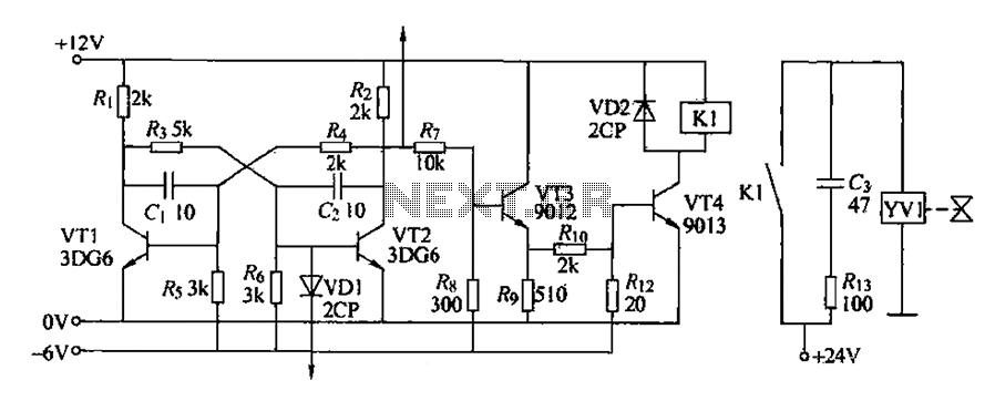
The circuit for detecting bad book binding is not illustrated. The solenoid valve is used to control the head of the YV1 mechanism for handling bad books. Under constant conditions, there is no positive signal indicating a bad book....