
Simple Li-Ion Battery Charger

The circuit described is a battery charging circuit utilizing the LP2951 voltage regulator, which is designed to safely charge single-cell lithium-ion batteries. The charging current is limited to approximately 100 mA, making it suitable for overnight charging applications. This current is within the acceptable range for lithium-ion batteries, which can typically handle charging currents up to 1C of their rated capacity.
The LP2951 is a low-dropout linear voltage regulator, allowing for efficient operation even when the input voltage is close to the output voltage. The circuit configuration includes a potentiometer (50kΩ) that provides an adjustable output voltage, allowing for fine-tuning between 4.08V and 4.26V. This adjustability is critical for accommodating different battery chemistries and capacities, ensuring optimal charging voltages for various lithium-ion cells.
Resistor values are chosen from the tens to hundreds of kilo-ohm range to minimize quiescent current, which is maintained at approximately 2 µA. This low off-state current is essential for battery-powered applications where energy conservation is a priority. The resistors should have a tolerance of 1% to maintain accuracy in the output voltage, ensuring reliable battery charging.
Capacitors are included in the design for stability, particularly capacitor C2, which is crucial in preventing oscillations in the output voltage. This is important for maintaining a steady charge to the battery and avoiding potential damage due to voltage spikes.
The inclusion of a diode (D1) from the 1N00x series serves as a blocking diode, preventing reverse current flow from the battery back into the LP2951 when the input voltage is disconnected. This feature protects the regulator and ensures safe operation of the circuit.
Overall, this circuit effectively balances performance and safety, making it a practical choice for charging single-cell lithium-ion batteries in various applications.Charging current is about 100+mA, which is the internally-limited maximum current of the LP2951. For those wondering, this is compatible with just about any single-cell li-ion battery since li-ion can generally accept a charging current of up to about 1c (i.e. charging current in mA equivalent to their capacity in mAh, so a 1100mAh li-ion cell can be charged at up to 1100mA and so on).
A lower charging current just brings about a correspondingly longer charge time. IMHO 100mA is quite low, low enough that the circuit can be used for an overnight charger for many typical single-cell li-ion batteries. The LP2951 regulator is manufactured by National Semiconductors. The choice of values is from an application note "Battery Charging", written by Chester Simpson. The resistors are deliberately kept at large orders of magnitude (tens/hundred Kohm and Mohm range) to keep the off-state current as low as possible, at about 2?A. Resistor tolerances should be kept at 1% for output voltage accuracy. The 50k pot allows for an output voltage range between 4.08V to 4.26V - thus allowing calibration as well as a choice between a charging voltage of 4.1V or 4.2V depending on the cell to be charged.
The capacitors are for stability, especially C2 which prevents the output from ringing/oscillating. Diode D1 can be any diode from the 1N00x series, whichever is conveniently available. It functions as a blocking diode, to prevent a back flow of current from the battery into the LP2951 when the input voltage is disconnected. 🔗 External reference
Related Circuits
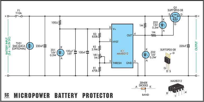
In May 2002, Silicon Chip introduced the "Battery Guardian," a project aimed at safeguarding 12V car batteries from over-discharge. This unit has gained significant popularity and remains available from kit suppliers. The new design does not replace the Battery...
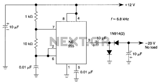
This DC negative-voltage generator based on the 555 produces a negative output voltage equal to approximately 2 times the DC supply voltage. The described circuit utilizes the popular 555 timer IC configured in an astable or monostable mode to generate...
This circuit is appropriate for any scenario where over-current protection is necessary. An example from the model train hobbyist community illustrates its importance. Experienced model train enthusiasts understand that locating the source of a short circuit can be quite...
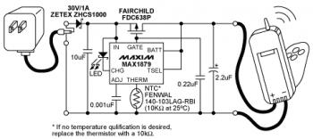
The diagram illustrates a Lithium-ion (Li-ion) battery charger designed using the MAX1879 single chip. This charger offers a simple and cost-effective solution for charging single-cell Li+ batteries without generating heat. The MAX1879, when paired with an AC linear transformer...
The GNU tools must be configured, built, and installed on the system. This chapter presents a simple example of using the GNU tools in an AVR project. After reviewing this chapter, users should gain a better understanding of how...
Typically, a charged lead-acid battery and a power inverter are utilized to ensure a well-organized holiday where family members can enjoy their electric and electronic devices. With rechargeable lead-acid batteries, it is often beneficial, if not essential, to determine...